VLSI: 2-4 Decoder Dataflow Modelling with Testbench
Verilog Code for 2-4 Decoder Dataflow Modelling
module decoder_2_to_4(
input a0,
input a1,
output d0,
output d1,
output d2,
output d3
);
assign an0 = ~ a0;
assign an1 = ~ a1;
assign d0 = an0 & an1;
assign d1 = a0 & an1;
assign d2 = an0 & a1;
assign d3 = a0 & a1;
endmodule
//Testbench code for 2-4 Decoder Dataflow Modelling
initial begin
//
Initialize Inputs
a0
= 0;a1 = 0;
// Wait 100
ns for global reset to finish
#100;
// Add
stimulus here
#100;
a0=1;a1=0;
#100;
a0=0;a1=1;
#100;
a0=1;a1=1;
end
Output:

Popular posts from this blog
1 to 4 DEMUX (Demultiplexer) Verilog CodeStructural/Gate Level Modelling with Testbench

Verilog Code for 1 to 4 DEMUX Structural/Gate Level Modelling 1-4 DEMUX module demux_1_to_4( input d, input s0, input s1, output y0, output y1, output y2, output y3 ); not(s1n,s1),(s0n,s0); and(y0,d,s0n,s1n),(y1,d,s0,s1n),(y2,d,s0n,s1),(y3,d,s0,s1); endmodule //Testbench code for 1 to 4 DEMUX Structural/Gate Level Modelling initial begin // Initialize Inputs d = 1; s0 = 0; s1 = 0; // Wait 100 ns for global reset to finish #100; // Add stimulus here #100;d = 1;s0 = 1;s1 = 0; #100;d = 1;s0 = ...
VLSI: 2 Bit Magnitude Comparator Dataflow Modelling

module mag_comp2bit( input a0, input a1, input b0, input b1, output p, // p = (a < b) output r, // r = (a > b) output q // q = (a = b) ); assign q = ((~a1) ^ (b1)) & (a0 & b0); assign p = (((~a1) & b1) | (b0 & (~a0) & (~a1)) | ((~a0) & b1 & b0)); assign r = ((a1 & (~b1)) | ((~b0) & a1 & a0) | (a0 & (~b1) & (~b0))); endmodule
VLSI: 1-4 DEMUX (Demultiplexer) Dataflow Modelling with Testbench

Verilog Code for 1-4 DEMUX Dataflow Modelling module demux_1_to_4( input d, input s0, input s1, output y0, output y1, output y2, output y3 ); assign s1n = ~ s1; assign s0n = ~ s0; assign y0 = d& s0n & s1n; assign y1 = d & s0 & s1n; assign y2 = d & s0n & s1; assign y3 = d & s0 & s1; endmodule //Testbench code for 1-4 DEMUX Dataflow Modelling initial begin // Initialize Inputs ...
VLSI: BCD to Excess 3 and Excess 3 to BCD Dataflow Modelling

module bcd_ex3_Dataflow( input a, input b, input c, input d, output w, output x, output y, output z ); assign w = (a | (b & c) | (b & d)); assign x = (((~b) & c) | ((~b) & d) | (b & (~c) & (~d))); assign y = ((c & d) | ((~c) & (~d))); assign z = ~d; endmodule Excess 3 to BCD: module ex3_to_bcd( input w, input x, input y, input z, output a, output b, output c, output d ); assign a = ((w & x) | (w & y & z)); assign b = (((~x) & (~y)) | ((~x) & (~z)) | (x & y & z)); assign c = (((~y) & z) | (y & (~z))); assign d = ~z; endmodule
VLSI: Half Subtractor and Full Subtractor Gate Level Modelling
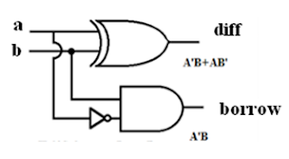
Half Subtractor: Verilog Module Code: module half_subtractor ( input a, input b, output diff output borr ); wire x; xor (diff,a,b); not (x,a); and (borr,x,b); endmodule Full Subtractor: Verilog Module Code: module full_subtractor ( input a, input b, input c, output diff output borr ); wire x,n2,z,n1; xor s1(x,a,b); not s3(n2,x); not s4(n1,c); and s5(y,n1,b); xor s2(diff,a,x); and s6(z,n2,a); or (borr,y,z); endmodule
Comments
Post a Comment