Posts
International Space Station: A Space Tour

ISS or International Space Station is a space-station orbiting Earth 400 Km above the sea level with speed 27000 Km/hr. It is a joint project of countries like USA, Russia, Japan, ESA and CSA. ISS completes one revolution around Earth in just 93 minutes. That means in 24 hours it takes 15 revolutions. Weight: 400 tons Breath: 109 m Length: 73 m ISS is divided in 2 parts, American Orbital Segment (USOS) and Russian Orbital Segment (ROS). Let's take a look at different modules of ISS: 1. Destiny: Destiny module is built by NASA. It is used for experiments and taking photos from 151 cm window. 2. Quest: Quest module is constructed by NASA. Quest contains Airlock system, and is used for spacewalks. Quest also houses spacewalk devices and spacesuits, also used as resting place for Astronauts. 3. Peer and Poshk: It ia a Russian docking module. This module contains 2 docking facility and auto fuel transfer facility. Soyuz and Progr...
Popular posts from this blog
VLSI: 1-4 DEMUX (Demultiplexer) Dataflow Modelling with Testbench

Verilog Code for 1-4 DEMUX Dataflow Modelling module demux_1_to_4( input d, input s0, input s1, output y0, output y1, output y2, output y3 ); assign s1n = ~ s1; assign s0n = ~ s0; assign y0 = d& s0n & s1n; assign y1 = d & s0 & s1n; assign y2 = d & s0n & s1; assign y3 = d & s0 & s1; endmodule //Testbench code for 1-4 DEMUX Dataflow Modelling initial begin // Initialize Inputs ...
VLSI: 4-1 MUX Dataflow Modelling with Testbench
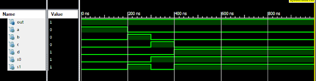
Verilog Code for 4-1 MUX Dataflow Modelling module m41(out, i0, i1, i2, i3, s0, s1); output out; input i0, i1, i2, i3, s0, s1; assign y0 = (i0 & (~s0) & (~s1)); assign y1 = (i1 & (~s0) & s1); assign y2 = (i2 & s0 & (~s1)); assign y3 = (i3 & s0 & s1); assign out = (y0 | y1 | y2 | y3); endmodule //Testbench code for 4-1 MUX Dataflow Modelling initial begin // Initialize Inputs a = 1;b = 0;c = 0;d = 0;s0 = 0;s1 = 0; ...
Verilog: 4 Bit Counter Behavioral Modelling using If Else Statement

Verilog Code for 4 Bit Counter Behavioral Modelling using If Else Statement module 4_bit_Count( input clock, reset, output [3:0]dout ); reg [3:0]dout; initial dout = 0; always @ (posedge (clock)) begin if (reset) dout <= 0; else dout <= dout + 1; end endmodule Xillinx Output: 4 Bit Counter Behavioral Modelling Response Also See: List of Verilog Programs
VLSI: 3-8 Decoder Dataflow Modelling with Testbench

Verilog Code for 3-8 Decoder Dataflow Modelling module decoder3_to_8( input x, input y, input z, output d0, output d1, output d2, output d3, output d4, output d5, output d6, output d7 ); assign d0 = xn & yn & zn; assign d1 = xn & yn & z; assign d2 = xn & y & zn; assign d3 = xn & y & z; assign d4 = x & yn & z; assign d5 = x & yn & z; assign d6 = x & y & zn; assign d7 = x & y & z; assign xn = ~ x; assign yn = ~ y; assign zn = ~ z; endmodule //Testbench code for 3-8 Decoder Dataflow Modelling ...
Full Subtractor Verilog Code in Structural/Gate Level Modelling with Testbench

Verilog Code for Full Subtractor Structural/Gate Level Modelling module full_sub(borrow,diff,a,b,c); output borrow,diff; input a,b,c; wire w1,w4,w5,w6; xor (diff,a,b,c); not n1(w1,a); and a1(w4,w1,b); and a2(w5,w1,c); and a3(w6,b,c); or o1(borrow,w4,w5,w6); endmodule //Testbench code for Full Subtractor Structural/Gate Level Modelling initial begin // Initialize Inputs a = 0; b = 0; c = 0; // Wait 100 ns for global reset to finish #100; // Add stimulus here #100; a = 0;b = 0;c = 1; #100; a = 0;b = 1;c = 0; #100; a = 0;b = 1;c = 1; #100; a = 1;b = 0;c = 0; #100; a = 1;b = 0;c = 1; #100; a = 1;b = 1;c = 0; #100; a = 1;b = 1;c = 1; end Output: RTL Schematic: Full Subtractor Verilog Other Verilog Programs: Go to Index of Verilog Programming