Posts
Filter Designer
Filter Designer Filter Designer tool can be used for designing Active Lowpass, Active Highpass and Active Bandpass Filters. Calculate the values of capacitors, resistors, Q values and frequencies of active filter. Note: Filter Designer Tool works best on Computers, we are currently optimizing this tool to work on smartphones. -------------------------------------------------------- Active Lowpass Calculator: 1. 2 Pole Active Lowpass with Unity Gain 2. 2 Pole Active Lowpass with Gain 3. 3 Pole Active Lowpass Filter Active Highpass Calculator: 1. 2 Pole Active Highpass with Unity Gain 2. 2 Pole Active Highpass with Gain 3. 3 Pole Active Highpass Filter Active Bandpass Calculator: 1. 2 Pole Active BandPass Filter 2. 4 Pole Active BandPass Filter 3. 6 Pole Active BandPass Filter Notch Filter Calculator: 1. 2 Op-Amp Notch Filter Calculator Sallen Key Filter Calculator: 1. Sallen Key Lowpass Butterworth Filter Calculator
2 Pole Active High Pass Filter with Unity Gain Calculator

2 Pole Active High Pass Filter Input Output Filter Type Butterworth Chebyshev 0.1 dB Bessel C1,C2,C3 (uF) 3dB Cutoff Freq (Hz) C1,C2,C3 (uF) R1 (K Ohms) R2 (K Ohms) Active Lowpass Calculator: 1. 2 Pole Active Lowpass with Unity Gain 2. 2 Pole Active Lowpass with Gain 3. 3 Pole Active Lowpass Filter Active Highpass Calculator: 1. 2 Pole Active Highpass with Unity Gain 2. 2 Pole Active Highpass with Gain 3. 3 Pole Active Highpass Filter Active Bandpass Calculator: 1. 2 Pole Active BandPass Filter 2. 4 Pole Active BandPass Filter 3. 6 Pole Active BandPass Filter
2 Pole High Pass Filter with Gain Calculator

2 Pole High Pass Filter with Gain Input Output Filter Type Butterworth Chebyshev 0.1 dB Bessel C (uF) 3dB Cutoff Freq (Hz) Voltage Gain R1 (K Ohms) R2 (K Ohms) C1 (uF) C2 (uF) C3 (uF) Active Lowpass Calculator: 1. 2 Pole Active Lowpass with Unity Gain 2. 2 Pole Active Lowpass with Gain 3. 3 Pole Active Lowpass Filter Active Highpass Calculator: 1. 2 Pole Active Highpass with Unity Gain 2. 2 Pole Active Highpass with Gain 3. 3 Pole Active Highpass Filter Active Bandpass Calculator: 1. 2 Pole Active BandPass Filter 2. 4 Pole Active BandPass Filter 3. 6 Pole Active BandPass Filter
Popular posts from this blog
Samir Palnitkar Solution Manual Free Download PDF of Verilog HDL
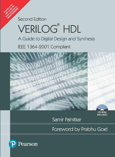
This is a solution guide to the exercises of the book "The Solution Manual of the Verilog HDL: A Guide to Digital Design and Synthesis by Samir Palnitkar". Following are the Solutions to Solution Manual on Verilog HDL: A Guide to Digital Design and Synthesis by Samir Palnitkar , exercises of all chapters in the book. Chapter 1 ----------------- No Exercises ---------------- Chapter 2 : Hierarchical Modeling Concepts Chapter 3 : Basic Concepts Chapter 4 : Modules and Ports Chapter 5: Gate-level Modeling Chapter 6 : Dataflow Modeling Chapter 7 : Behavioral Modeling Chapter 8 : Tasks and Functions Download Solution Manual: Click on this link (Mega.nz Link) [Solution Manual to Verilog HDL: A Guide to Digital Design and Synthesis by Samir Palnitkar] Preview of Solution Manual: For Verilog Programs: Go to Index of Verilog Programming Tags: Verilog HDL solutio...
VLSI: 8-3 Encoder Dataflow Modelling with Testbench
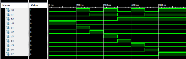
Verilog Code for 8-3 Encoder Dataflow Modelling module encoder_8_to_3( input d0, input d1, input d2, input d3, input d4, input d5, input d6, input d7, output q0, output q1, output q2 ); assign q0 = ( d1 | d3 | d5 | d7 ); assign q1 = ( d2 | d3 | d6 | d7 ); assign q2 = ( d4 | d6 | d5 | d7 ); endmodule //Testbench code for 8-3 Encoder Dataflow Modelling initial begin ...
VLSI: 4-1 MUX Dataflow Modelling with Testbench
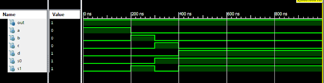
Verilog Code for 4-1 MUX Dataflow Modelling module m41(out, i0, i1, i2, i3, s0, s1); output out; input i0, i1, i2, i3, s0, s1; assign y0 = (i0 & (~s0) & (~s1)); assign y1 = (i1 & (~s0) & s1); assign y2 = (i2 & s0 & (~s1)); assign y3 = (i3 & s0 & s1); assign out = (y0 | y1 | y2 | y3); endmodule //Testbench code for 4-1 MUX Dataflow Modelling initial begin // Initialize Inputs a = 1;b = 0;c = 0;d = 0;s0 = 0;s1 = 0; ...
Verilog: 4 - 2 Encoder Structural/Gate Level Modelling with Testbench
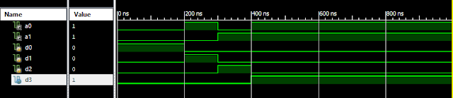
Verilog Code for 4-2 Encoder Structural/Gate Level Modelling module encode_4_to_2( input d0,d1,d2,d3, output a0,a1 ); wire x,y,z; not g1(x,d2); and g2(y,x,d1); or g3(a0,y,d3); or g4(a1,d2,d3); endmodule //Testbench code for 4-2 Encoder Structural/Gate Level Modelling initial begin // Initialize Inputs d0 = 1;d1 = 0;d2 = 0;d3 = 0; // Wait 100 ns for global reset to finish #100; // Add stimulus here #100;d0 = 0;d1 = 1;d2 = 0;d3 = 0; #100;d0 = 0;d1 = 0;d2 = 1;d3 = 0; #100;d0 = 0;d1 = 0;d2 = 0;d3 = 1; end Output: Verilog 4-2 Encoder Response Other Verilog Programs: Go to Index of Verilog Programming
1 to 4 DEMUX (Demultiplexer) Verilog CodeStructural/Gate Level Modelling with Testbench

Verilog Code for 1 to 4 DEMUX Structural/Gate Level Modelling 1-4 DEMUX module demux_1_to_4( input d, input s0, input s1, output y0, output y1, output y2, output y3 ); not(s1n,s1),(s0n,s0); and(y0,d,s0n,s1n),(y1,d,s0,s1n),(y2,d,s0n,s1),(y3,d,s0,s1); endmodule //Testbench code for 1 to 4 DEMUX Structural/Gate Level Modelling initial begin // Initialize Inputs d = 1; s0 = 0; s1 = 0; // Wait 100 ns for global reset to finish #100; // Add stimulus here #100;d = 1;s0 = 1;s1 = 0; #100;d = 1;s0 = ...