Posts
Pressure Converter
Pressure Equivalents First, type the number you wish converted here: Then, click radio buttons for desired conversion: Fm: megadynes/ sq cm kg/ sq cm lb/ sq in atmos- pheres Hg* Meters Hg* Inches H2O* Meters H20* Inches H20* Feet To: megadynes/ sq cm kg/ sq cm lb/ sq in atmos- pheres Hg* Meters Hg* Inches H2O* Meters H2O* Inches H20* Feet *Standard columns of Mercury at 0 o C, g = 980.665 cm/sec/sec Standard columns of Water at 60 o F, g = 32.1756 ft/sec/sec
Weight Converter
Weight Converter Select unit from Drop Down Menu and enter the a number in the box beside it, Click on Convert button. Gram Kilogram Ounce Pound U.S. Ton Gram: Kilogram: Ounce: Pound: U.S. Ton:
Loan Calculator
The results of this loan payment calculator are for comparison purposes only. They will be a close approximation of actual loan repayments if available at the terms entered, from a financial institution. To use, enter values for the Loan Amount, Number of Months for Loan, and the Interest Rate (e.g. 7.25), and click the Calculate button. Clicking the Reset button will clear entered values. Description Data Entry Loan Amount Loan Length in Months Interest Rate Monthly Payment Calculated Enter only numeric values (no commas), using decimal points where needed. Non-numeric values will cause errors.
Body Mass Index (BMI) Calculator
Your Weight(kg): Your Height(cm): Your BMI: This Means: Other Online Tools: Temperature Converter Length Converter World Clock
Temperature Converter
Type a value in any of the fields and click Convert to convert between Temperature measurements: Celsius: Fahrenheit: Kelvin: Other Online Tools: Length Converter BMI Calculator World Clock
Length Converter
Type a value in any of the fields and click Convert to convert between Length measurements: Centimeter: Inch: Feet: Meter: Yard: Kilometer: Miles: Other Online Tools: Temperature Converter BMI Calculator World Clock
VLSI: Half Subtractor and Full Subtractor Gate Level Modelling
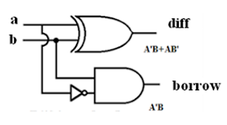
Half Subtractor: Verilog Module Code: module half_subtractor ( input a, input b, output diff output borr ); wire x; xor (diff,a,b); not (x,a); and (borr,x,b); endmodule Full Subtractor: Verilog Module Code: module full_subtractor ( input a, input b, input c, output diff output borr ); wire x,n2,z,n1; xor s1(x,a,b); not s3(n2,x); not s4(n1,c); and s5(y,n1,b); xor s2(diff,a,x); and s6(z,n2,a); or (borr,y,z); endmodule
VLSI: Logic Gates Gate Level Modelling
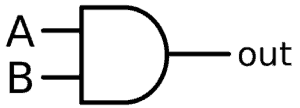
AND Gate: Verilog Module Code: module and_gate ( input a, input b, output c ); and (c,a,b); endmodule OR Gate: Verilog Module Code: module or_gate ( input a, input b, output c ); or (c,a,b); endmodule NAND Gate: Verilog Module Code: module nand_gate ( input a, input b, output c ); nand (c,a,b); endmodule NOR Gate: Verilog Module Code: module nor_gate ( input a, input b, output c ); nor (c,a,b); endmodule XOR Gate: Verilog Module Code: module xor_gate ( input a, ...
VLSI: 2 Bit Magnitude Comparator Dataflow Modelling

module mag_comp2bit( input a0, input a1, input b0, input b1, output p, // p = (a < b) output r, // r = (a > b) output q // q = (a = b) ); assign q = ((~a1) ^ (b1)) & (a0 & b0); assign p = (((~a1) & b1) | (b0 & (~a0) & (~a1)) | ((~a0) & b1 & b0)); assign r = ((a1 & (~b1)) | ((~b0) & a1 & a0) | (a0 & (~b1) & (~b0))); endmodule
VLSI: BCD to Excess 3 and Excess 3 to BCD Dataflow Modelling

module bcd_ex3_Dataflow( input a, input b, input c, input d, output w, output x, output y, output z ); assign w = (a | (b & c) | (b & d)); assign x = (((~b) & c) | ((~b) & d) | (b & (~c) & (~d))); assign y = ((c & d) | ((~c) & (~d))); assign z = ~d; endmodule Excess 3 to BCD: module ex3_to_bcd( input w, input x, input y, input z, output a, output b, output c, output d ); assign a = ((w & x) | (w & y & z)); assign b = (((~x) & (~y)) | ((~x) & (~z)) | (x & y & z)); assign c = (((~y) & z) | (y & (~z))); assign d = ~z; endmodule
VLSI: 4-2 Encoder Dataflow Modelling

module Four_Two_Encoder( input a0, input a1, input a2, input a3, output e0, output e1, output v ); assign e0 = a1 | a3; assign e1 = a2 | a3; assign v = a0; endmodule
VLSI: 2-4 Decoder Dataflow Modelling

module Two_Four_Decoder( input a0, input a1, output d0, output d1, output d2, input d3 ); assign d0 = ((~a0) & (~a1)); assign d1 = ((~a0) & a1); assign d2 = (a0 & (~a1)); assign d3 = (a0 & a1); endmodule
VLSI: Gray to Binary and Binary to Gray Dataflow Modelling

Gray to Binary: module Gray_to_Binary( input g1, input g2, input g3, input g4, output b1, output b2, output b3, output b4 ); assign b4 = g4; assign b3 = b4 ^ g3; assign b2 = b3 ^ g2; assign b1 = b2 ^ g1; endmodule Binary to Gray: module Binary_to_Gray( input b1, input b2, input b3, input b4, output g1, output g2, output g3, output g4 ); assign g1 = b1; assign g2 = b1 ^ b2; assign g3 = b2 ^ b3; assign g4 = b3 ^ b4; endmodule
VLSI: 4-1 Multiplexer (MUX) Dataflow Modelling
module Four_to_One_MUX( input s0, input s1, input i0, input i1, input i2, input i3, output out ); assign y0 = (i0 & (~s0) & (~s1)); assign y1 = (i1 & (~s0) & s1); assign y2 = (i2 & s0 & (~s1)); assign y3 = (i3 & s0 & s1); assign out = (y0 | y1 | y2 | y3); endmodule MUX using Conditional Statement: module Four_to_One_MUX( input s0, input s1, input i0, input i1, input i2, input i3, output out ); assign out = s0 ? (s1 ? i3 : i2) : (s1 ? i1 : i0); endmodule
VLSI: 4-1 MUX Gate Level Modelling
module FourtoOneMUX( input s1, input s0, input i0, input i1, input i2, input i3, output out ); wire sn0,sn1; wire y0,y1,y2,y3; not n1(s1n,s1); not n2(s0n,s0); and a1(y0,i0,sn0,sn1); and a2(y1,i1,sn0,s1); and a3(y2,i2,s0,sn1); and a4(y3,i3,s0,s1); or o1(out,y0,y1,y2,y3); endmodule
VLSI: Half Adder and Full Adder Gate Level Modelling
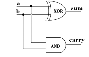
Half Adder: module HalfAdder( input A, input B, output sum, output carry ); xor (sum,A,B); and (carry,A,B); endmodule Full Adder: module FullAdder( input A, input B, input Cin, output sum, output carry ); wire a1, a2, a3; xor g1(a1,A,B); and g4(a2,A,B); and g3(a3,a1,Cin); or g5(carry,a2,a3); xor g2(sum,a1,Cin); endmodule
VLSI: Binary to Gray and Gray to Binary Converter Gate Level Modelling
Binary to Gray: module Binary_to_Gray( input b1, input b2, input b3, input b4, output g1, output g2, output g3, output g4 ); xor u1(g2,b1,b2); xor u2(g3,b2,b3); xor u3(g4,b4,b3); buf u4(g1,b1); endmodule Gray to Binary: module GraytoBinary( input g1, input g2, input g3, input g4, output b1, output b2, output b3, output b4 ); xor u1(b4,g1,b3); xor u2(b3,g3,b2); xor u3(b2,g2,g1); buf u4(b1,g1); endmodule
VLSI: Encoder Gate Level Modelling
module Encoder(d0,d1,d2,d3,d4,d5,d6,d7,a,b,c); input d0,d1,d2,d3,d4,d5,d6,d7; output a,b,c; or (a,d4,d5,d6,d7); or (b,d2,d3,d6,d7); or (c,d1,d3,d5,d7); endmodule
VLSI: 8-1 Demultiplexer Dataflow Modelling
module Demultiplexer(in,s0,s1,s2,d0,d1,d2,d3,d4,d5,d6,d7); input in,s0,s1,s2; output d0,d1,d2,d3,d4,d5,d6,d7; assign d0=(in & ~s2 & ~s1 &~s0), d1=(in & ~s2 & ~s1 &s0), d2=(in & ~s2 & s1 &~s0), d3=(in & ~s2 & s1 &s0), d4=(in & s2 & ~s1 &~s0), d5=(in & s2 & ~s1 &s0), d6=(in & s2 & s1 &~s0), d7=(in & s2 & s1 &s0); endmodule
VLSI: Carry Look Ahead Adder
module CLA_Adder(a,b,cin,sum,cout); input [3:0] a,b; input cin; output [3:0] sum; output cout; wire p0,p1,p2,p3,g0,g1,g2,g3,c1,c2,c3,c4; assign p0=(a[0]^b[0]), p1=(a[1]^b[1]), p2=(a[2]^b[2]), p3=(a[3]^b[3]); assign g0=(a[0]&b[0]), g1=(a[1]&b[1]), g2=(a[2]&b[2]), g3=(a[3]&b[3]); assign c0=cin, c1=g0|(p0&cin), c2=g1|(p1&g0)|(p1&p0&cin), c3=g2|(p2&g1)|(p2&p1&g0)|(p1&p1&p0&cin), c4=g3|(p3&g2)|(p3&p2&g1)|(p3&p2&p1&g0)|(p3&p2&p1&p0&cin); assign sum[0]=p0^c0, sum[1]=p1^c1, sum[2]=p2^c2, sum[3]=p3^c3; assign cout=c4; endmodule
VLSI: 4 Bit Adder and 4 Bit Subtractor
4 Bit Adder: module MultibitAdder(a,b,cin,sum,cout); input [3:0] a,b; input cin; output [3:0]sum; output cout; assign {cout,sum}=a+b+cin; endmodule 4 Bit Subtractor: module MultibitSubstractor(a,b,bin,difference,bout); input [3:0] a,b; input bin; output [3:0]difference; output bout; assign {bout,difference}=a-b-bin; endmodule
VLSI: Logic Gates Dataflow Modelling
AND Gate: Verilog Module Code: module and_gate ( input a, input b, output c ); assign c = a & b; endmodule OR Gate: Verilog Module Code: module or_gate ( input a, input b, output c ); assign c = a | b; endmodule NAND Gate: Verilog Module Code: module nand_gate ( input a, input b, output c ); assign c = ~ ( a & b ); endmodule NOR Gate: Verilog Module Code: module nor_gate ( input a, input b, output c ); assign c = ~ ( a | b ); endmodule XOR Gate: Verilog Module Code: module xor_gate ( ...
Popular posts from this blog
Samir Palnitkar Solution Manual Free Download PDF of Verilog HDL
This is a solution guide to the exercises of the book "The Solution Manual of the Verilog HDL: A Guide to Digital Design and Synthesis by Samir Palnitkar". Following are the Solutions to Solution Manual on Verilog HDL: A Guide to Digital Design and Synthesis by Samir Palnitkar , exercises of all chapters in the book. Chapter 1 ----------------- No Exercises ---------------- Chapter 2 : Hierarchical Modeling Concepts Chapter 3 : Basic Concepts Chapter 4 : Modules and Ports Chapter 5: Gate-level Modeling Chapter 6 : Dataflow Modeling Chapter 7 : Behavioral Modeling Chapter 8 : Tasks and Functions Download Solution Manual: Click on this link (Mega.nz Link) [Solution Manual to Verilog HDL: A Guide to Digital Design and Synthesis by Samir Palnitkar] Preview of Solution Manual: For Verilog Programs: Go to Index of Verilog Programming Tags: Verilog HDL solutio...
VLSI: 4-1 MUX Dataflow Modelling with Testbench
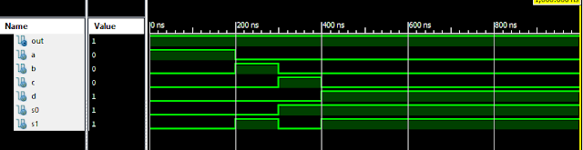
Verilog Code for 4-1 MUX Dataflow Modelling module m41(out, i0, i1, i2, i3, s0, s1); output out; input i0, i1, i2, i3, s0, s1; assign y0 = (i0 & (~s0) & (~s1)); assign y1 = (i1 & (~s0) & s1); assign y2 = (i2 & s0 & (~s1)); assign y3 = (i3 & s0 & s1); assign out = (y0 | y1 | y2 | y3); endmodule //Testbench code for 4-1 MUX Dataflow Modelling initial begin // Initialize Inputs a = 1;b = 0;c = 0;d = 0;s0 = 0;s1 = 0; ...
Verilog: 1to 8 DeMultiplexer (1-8 DEMUX) Dataflow Modelling with Testbench Code
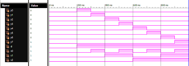
Verilog Code for 1 to 8 DeMultiplexer Dataflow Modelling module demux_1_to_8( input d, input s0, input s1, input s2, output y0, output y1, output y2, output y3, output y4, output y5, output y6, output y7 ); assign s0n = ~ s0; assign s1n = ~ s1; assign s2n = ~ s2; assign y0 = d & s0n & s1n & s2n; assign y1 = d & s0 & s1n & s2n; assign y2 = d & s0n & s1 & s2n; assign y3 = d & s0 & s1 & s2n; assign y4 = d & s0n & s1n & s2; assign y5 = d & s0 & s1n & s2; assign y6 = d & s0n & s1 & s2; assign y7 = d & s0 & s1 & s2; endmodule //Testbench code for 1-8 DEMUX Dataflow Modelling initial begin // Initialize Inputs d = 0;s0 = 0;s1 = 0;s2 = 0; // Wait 100 ns for global reset to finish #100; // Add stimulus here #100; d = 1;s0 = 0;s1 = 0;s2 = 0; #100; d = 1;s0 = 1;s1 = 0;s2 = 0; #100; d = 1;s0 = 0;s1 = 1;s2 = 0; #100; d = 1;s0 = 1;s1 = 1;s2 = 0; #100; d = 1;s0 = 0;s1 = 0;s2 = 1; ...
VLSI: 8-3 Encoder Dataflow Modelling with Testbench

Verilog Code for 8-3 Encoder Dataflow Modelling module encoder_8_to_3( input d0, input d1, input d2, input d3, input d4, input d5, input d6, input d7, output q0, output q1, output q2 ); assign q0 = ( d1 | d3 | d5 | d7 ); assign q1 = ( d2 | d3 | d6 | d7 ); assign q2 = ( d4 | d6 | d5 | d7 ); endmodule //Testbench code for 8-3 Encoder Dataflow Modelling initial begin ...
Full Subtractor Verilog Code in Structural/Gate Level Modelling with Testbench

Verilog Code for Full Subtractor Structural/Gate Level Modelling module full_sub(borrow,diff,a,b,c); output borrow,diff; input a,b,c; wire w1,w4,w5,w6; xor (diff,a,b,c); not n1(w1,a); and a1(w4,w1,b); and a2(w5,w1,c); and a3(w6,b,c); or o1(borrow,w4,w5,w6); endmodule //Testbench code for Full Subtractor Structural/Gate Level Modelling initial begin // Initialize Inputs a = 0; b = 0; c = 0; // Wait 100 ns for global reset to finish #100; // Add stimulus here #100; a = 0;b = 0;c = 1; #100; a = 0;b = 1;c = 0; #100; a = 0;b = 1;c = 1; #100; a = 1;b = 0;c = 0; #100; a = 1;b = 0;c = 1; #100; a = 1;b = 1;c = 0; #100; a = 1;b = 1;c = 1; end Output: RTL Schematic: Full Subtractor Verilog Other Verilog Programs: Go to Index of Verilog Programming