Posts
Showing posts with the label Exoplanets
Latest Post
Space Facts: Part 1 - Goldilock Zone, Exoplanets, Brown Dwarf and Dwarf Planets
- Get link
- X
- Other Apps
Welcome to Stellar Space Stellar Space blog is made to distribute the unknown knowledge regarding space science which we normally don't find in books and also not in any movies. this blog contains many details regarding Planets, stars, Exoplanets, Cosmic voids, Dark matter, Gravitational waves, Cosmology, Space horizons and many more things. Let's start with Space Fact series... Space Facts: Part 1 1. What is Goldilock Zone: Goldilock zone is also called Habitable Zone. it is the zone in which humans can survive. Earth is situated in Goldilock zone of our solar system. Many other solar systems too have Goldilock Zone. For example Kepler 186F planet is also situated in Goldilock zone of a distant solar system. Space Scientists usually try to find such planets because these planets have maximum possibility of holding life. 2. Exoplanets: Exoplanets are planets which do not reside in any of the solar system and freely wander in universe, certain planets a...
Popular posts from this blog
Verilog: 8 to 1 Multiplexer (8-1 MUX) Dataflow Modelling with Testbench Code
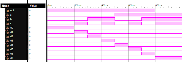
Verilog Code for 8 to 1 Multiplexer Dataflow Modelling module mux_8to1( input a, input b, input c, input D0, input D1, input D2, input D3, input D4, input D5, input D6, input D7, output out, ); module m81( output out, input D0, D1, D2, D3, D4, D5, D6, D7, S0, S1, S2); assign S1bar=~S1; assign S0bar=~S0; assign S2bar=~S2; assign out = (D0 & S2bar & S1bar & S0bar) | (D1 & S2bar & S1bar & S0) | (D2 & S2bar & S1 & S0bar) + (D3 & S2bar & S1 & S0) + (D4 & S2 & S1bar & S0bar) + (D5 & S2 & S1bar & S0) + (D6 & S2 & S1 & S0bar) + (D7 & S2 & S1 & S0); endmodule //Testbench code for 8-1 MUX Dataflow Modelling initial begin // Initialize Inputs a= 0;b = 0;c = 0;D0 = 1;D1 = 0;D2 = 0;D3 = 0;D4 = 0;D5 = 0;D6 = 0;D7 = 0; // Wait 100 ns for global reset to finish #100; // Add stimulus here #100; a = 0;b = 0;c = 1;d0 = ...
VLSI: 1-4 DEMUX (Demultiplexer) Dataflow Modelling with Testbench
Verilog Code for 1-4 DEMUX Dataflow Modelling module demux_1_to_4( input d, input s0, input s1, output y0, output y1, output y2, output y3 ); assign s1n = ~ s1; assign s0n = ~ s0; assign y0 = d& s0n & s1n; assign y1 = d & s0 & s1n; assign y2 = d & s0n & s1; assign y3 = d & s0 & s1; endmodule //Testbench code for 1-4 DEMUX Dataflow Modelling initial begin // Initialize Inputs ...
VLSI: 4-1 MUX Dataflow Modelling with Testbench
Verilog Code for 4-1 MUX Dataflow Modelling module m41(out, i0, i1, i2, i3, s0, s1); output out; input i0, i1, i2, i3, s0, s1; assign y0 = (i0 & (~s0) & (~s1)); assign y1 = (i1 & (~s0) & s1); assign y2 = (i2 & s0 & (~s1)); assign y3 = (i3 & s0 & s1); assign out = (y0 | y1 | y2 | y3); endmodule //Testbench code for 4-1 MUX Dataflow Modelling initial begin // Initialize Inputs a = 1;b = 0;c = 0;d = 0;s0 = 0;s1 = 0; ...
VLSI: Half Subtractor and Full Subtractor Gate Level Modelling
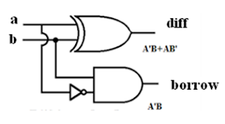
Half Subtractor: Verilog Module Code: module half_subtractor ( input a, input b, output diff output borr ); wire x; xor (diff,a,b); not (x,a); and (borr,x,b); endmodule Full Subtractor: Verilog Module Code: module full_subtractor ( input a, input b, input c, output diff output borr ); wire x,n2,z,n1; xor s1(x,a,b); not s3(n2,x); not s4(n1,c); and s5(y,n1,b); xor s2(diff,a,x); and s6(z,n2,a); or (borr,y,z); endmodule
Full Subtractor Verilog Code in Structural/Gate Level Modelling with Testbench
Verilog Code for Full Subtractor Structural/Gate Level Modelling module full_sub(borrow,diff,a,b,c); output borrow,diff; input a,b,c; wire w1,w4,w5,w6; xor (diff,a,b,c); not n1(w1,a); and a1(w4,w1,b); and a2(w5,w1,c); and a3(w6,b,c); or o1(borrow,w4,w5,w6); endmodule //Testbench code for Full Subtractor Structural/Gate Level Modelling initial begin // Initialize Inputs a = 0; b = 0; c = 0; // Wait 100 ns for global reset to finish #100; // Add stimulus here #100; a = 0;b = 0;c = 1; #100; a = 0;b = 1;c = 0; #100; a = 0;b = 1;c = 1; #100; a = 1;b = 0;c = 0; #100; a = 1;b = 0;c = 1; #100; a = 1;b = 1;c = 0; #100; a = 1;b = 1;c = 1; end Output: RTL Schematic: Full Subtractor Verilog Other Verilog Programs: Go to Index of Verilog Programming


