Latest Post
Space Facts: Part 7 - Mysterious Sun, Multiverse, Dark Matter
- Get link
- X
- Other Apps
Mysterious Sun:
Even though we know Sun from centuries, there are many mysteries of Sun remained unsolved. Most popular mystery is regarding Corona of Sun. Corona is outer layer of Sun's atmosphere. Corona is hotter than the inner layer Chromosphere.
Sun's visible surface Photosphere has temperature 5800°C. Outer layer of Photosphere is Chromosphere. Temperature of Chromosphere is estimated to be 4000°C. But astonishing fact is that Corona (outermost layer of Sun) is 3 million ℃. This is not possible if Heat Transfer laws are to be considered. To study about Sun in detail NASA sent a probe in 2018, ISRO will send Aaditya L1 probe to Langlargian L1 point from where Aaditya L1 will study the properties of Sun.
Are there Multiple Universes?
Multiverse theory is Hypothetical theory giving arguments of multiple universe are present in space-time. Many different Multiverse theory are formed. According to one, different universe may have different laws of Physics. As it could happen that in different universes the properties of subatomic particles may be different.
The Dark Matter Mystery:
Today we do not know what exactly is Dark Matter made up of, but we know it's presence and it's effects.
Some scientists believe that dark matter is made up of Neutrinos. Let's take an example proving presence of Dark Matter.
Andromeda is our neighbouring galaxy. Outer solar system of Andromeda are revolving around it's black hole at speed higher than expected.
To understand this case scientists calculated the total force acting on outer solar systems. This force is gravity of inner solar system and black hole. Surprisingly the force calculated was not enough to move outer solar system with speed in which they are revolving around. This extra force acting was from dark matter.
Dark matter has mass but it is not luminous, so we are not able to observe it even through powerful telescopes and observatories. What dark matter is formed of is not known, but we are sure it possess gravity.
- Get link
- X
- Other Apps
Popular posts from this blog
Verilog: 8 to 1 Multiplexer (8-1 MUX) Dataflow Modelling with Testbench Code
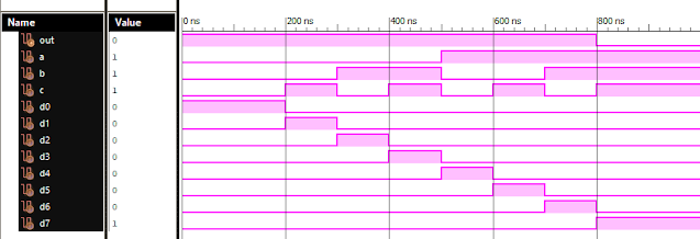
Verilog Code for 8 to 1 Multiplexer Dataflow Modelling module mux_8to1( input a, input b, input c, input D0, input D1, input D2, input D3, input D4, input D5, input D6, input D7, output out, ); module m81( output out, input D0, D1, D2, D3, D4, D5, D6, D7, S0, S1, S2); assign S1bar=~S1; assign S0bar=~S0; assign S2bar=~S2; assign out = (D0 & S2bar & S1bar & S0bar) | (D1 & S2bar & S1bar & S0) | (D2 & S2bar & S1 & S0bar) + (D3 & S2bar & S1 & S0) + (D4 & S2 & S1bar & S0bar) + (D5 & S2 & S1bar & S0) + (D6 & S2 & S1 & S0bar) + (D7 & S2 & S1 & S0); endmodule //Testbench code for 8-1 MUX Dataflow Modelling initial begin // Initialize Inputs a= 0;b = 0;c = 0;D0 = 1;D1 = 0;D2 = 0;D3 = 0;D4 = 0;D5 = 0;D6 = 0;D7 = 0; // Wait 100 ns for global reset to finish #100; // Add stimulus here #100; a = 0;b = 0;c = 1;d0 = ...
VLSI: 8-3 Encoder Dataflow Modelling with Testbench
Verilog Code for 8-3 Encoder Dataflow Modelling module encoder_8_to_3( input d0, input d1, input d2, input d3, input d4, input d5, input d6, input d7, output q0, output q1, output q2 ); assign q0 = ( d1 | d3 | d5 | d7 ); assign q1 = ( d2 | d3 | d6 | d7 ); assign q2 = ( d4 | d6 | d5 | d7 ); endmodule //Testbench code for 8-3 Encoder Dataflow Modelling initial begin ...
VLSI: 1-4 DEMUX (Demultiplexer) Dataflow Modelling with Testbench
Verilog Code for 1-4 DEMUX Dataflow Modelling module demux_1_to_4( input d, input s0, input s1, output y0, output y1, output y2, output y3 ); assign s1n = ~ s1; assign s0n = ~ s0; assign y0 = d& s0n & s1n; assign y1 = d & s0 & s1n; assign y2 = d & s0n & s1; assign y3 = d & s0 & s1; endmodule //Testbench code for 1-4 DEMUX Dataflow Modelling initial begin // Initialize Inputs ...
VLSI: 4-1 MUX Dataflow Modelling with Testbench
Verilog Code for 4-1 MUX Dataflow Modelling module m41(out, i0, i1, i2, i3, s0, s1); output out; input i0, i1, i2, i3, s0, s1; assign y0 = (i0 & (~s0) & (~s1)); assign y1 = (i1 & (~s0) & s1); assign y2 = (i2 & s0 & (~s1)); assign y3 = (i3 & s0 & s1); assign out = (y0 | y1 | y2 | y3); endmodule //Testbench code for 4-1 MUX Dataflow Modelling initial begin // Initialize Inputs a = 1;b = 0;c = 0;d = 0;s0 = 0;s1 = 0; ...
Verilog: 1to 8 DeMultiplexer (1-8 DEMUX) Dataflow Modelling with Testbench Code
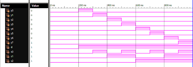
Verilog Code for 1 to 8 DeMultiplexer Dataflow Modelling module demux_1_to_8( input d, input s0, input s1, input s2, output y0, output y1, output y2, output y3, output y4, output y5, output y6, output y7 ); assign s0n = ~ s0; assign s1n = ~ s1; assign s2n = ~ s2; assign y0 = d & s0n & s1n & s2n; assign y1 = d & s0 & s1n & s2n; assign y2 = d & s0n & s1 & s2n; assign y3 = d & s0 & s1 & s2n; assign y4 = d & s0n & s1n & s2; assign y5 = d & s0 & s1n & s2; assign y6 = d & s0n & s1 & s2; assign y7 = d & s0 & s1 & s2; endmodule //Testbench code for 1-8 DEMUX Dataflow Modelling initial begin // Initialize Inputs d = 0;s0 = 0;s1 = 0;s2 = 0; // Wait 100 ns for global reset to finish #100; // Add stimulus here #100; d = 1;s0 = 0;s1 = 0;s2 = 0; #100; d = 1;s0 = 1;s1 = 0;s2 = 0; #100; d = 1;s0 = 0;s1 = 1;s2 = 0; #100; d = 1;s0 = 1;s1 = 1;s2 = 0; #100; d = 1;s0 = 0;s1 = 0;s2 = 1; ...


Comments
Post a Comment