Latest Post
Space Facts: Part 6 - Apogee and Perigee
- Get link
- X
- Other Apps
What is Apogee and Perigee ?
The point of orbit nearest to Earth is Perigee and farthest from Earth is called Apogee. Satellites sent from PSLV rockets follow this system as the speed of PSLV rockets is less than 11.2 Km/sec. Here spacecrafts have to change different orbits (also known as Orbit Maneuvers) around Earth to get speed of 11.2 Km/sec. By achieving speed higher than 11.2 Km/sec we spacecrafts can escape Earth's gravity, this velocity is called "Escape Velocity".
GSLV MK III rockets have speed 11.2 Km/sec, so spacecrafts do not have to change different orbits and spacecrafts are directly inserted into space.
Mangalyaan had to undergo Orbital Maneuvers as it was launched from PSLV rocket. If it was to launch from GSLV MK III, Mangalyaan would take less time to reach Mars than it took with PSLV.
In Apogee and Perigee the orbit is of elliptical shape. When spacecraft travels from Apogee to Perigee it gains velocity die to gravity of Earth. Orbit of spacecraft becomes more elliptical. After completion of one round, again when spacecraft travels from Apogee to Perigee it gains more velocity than earlier giving more elliptical orbit. This transition is called Orbital Maneuver, where the orbits are changed.
These Orbital Maneuvering is done till escape velocity is achieved and spacecraft leaves Earth's gravity.
When spacecraft enters in Mars' gravity, it has to be slowed down, otherwise it will fly-by across Mars and leave the desired trajectory. For slowing down the spacecraft, engine thrusters are used and spacecraft is settled in desired orbit.
- Get link
- X
- Other Apps
Popular posts from this blog
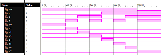
Verilog: 8 to 1 Multiplexer (8-1 MUX) Dataflow Modelling with Testbench Code
Verilog Code for 8 to 1 Multiplexer Dataflow Modelling module mux_8to1( input a, input b, input c, input D0, input D1, input D2, input D3, input D4, input D5, input D6, input D7, output out, ); module m81( output out, input D0, D1, D2, D3, D4, D5, D6, D7, S0, S1, S2); assign S1bar=~S1; assign S0bar=~S0; assign S2bar=~S2; assign out = (D0 & S2bar & S1bar & S0bar) | (D1 & S2bar & S1bar & S0) | (D2 & S2bar & S1 & S0bar) + (D3 & S2bar & S1 & S0) + (D4 & S2 & S1bar & S0bar) + (D5 & S2 & S1bar & S0) + (D6 & S2 & S1 & S0bar) + (D7 & S2 & S1 & S0); endmodule //Testbench code for 8-1 MUX Dataflow Modelling initial begin // Initialize Inputs a= 0;b = 0;c = 0;D0 = 1;D1 = 0;D2 = 0;D3 = 0;D4 = 0;D5 = 0;D6 = 0;D7 = 0; // Wait 100 ns for global reset to finish #100; // Add stimulus here #100; a = 0;b = 0;c = 1;d0 = ...
VLSI: 8-3 Encoder Dataflow Modelling with Testbench
Verilog Code for 8-3 Encoder Dataflow Modelling module encoder_8_to_3( input d0, input d1, input d2, input d3, input d4, input d5, input d6, input d7, output q0, output q1, output q2 ); assign q0 = ( d1 | d3 | d5 | d7 ); assign q1 = ( d2 | d3 | d6 | d7 ); assign q2 = ( d4 | d6 | d5 | d7 ); endmodule //Testbench code for 8-3 Encoder Dataflow Modelling initial begin ...
VLSI: 1-4 DEMUX (Demultiplexer) Dataflow Modelling with Testbench
Verilog Code for 1-4 DEMUX Dataflow Modelling module demux_1_to_4( input d, input s0, input s1, output y0, output y1, output y2, output y3 ); assign s1n = ~ s1; assign s0n = ~ s0; assign y0 = d& s0n & s1n; assign y1 = d & s0 & s1n; assign y2 = d & s0n & s1; assign y3 = d & s0 & s1; endmodule //Testbench code for 1-4 DEMUX Dataflow Modelling initial begin // Initialize Inputs ...
VLSI: 4-1 MUX Dataflow Modelling with Testbench
Verilog Code for 4-1 MUX Dataflow Modelling module m41(out, i0, i1, i2, i3, s0, s1); output out; input i0, i1, i2, i3, s0, s1; assign y0 = (i0 & (~s0) & (~s1)); assign y1 = (i1 & (~s0) & s1); assign y2 = (i2 & s0 & (~s1)); assign y3 = (i3 & s0 & s1); assign out = (y0 | y1 | y2 | y3); endmodule //Testbench code for 4-1 MUX Dataflow Modelling initial begin // Initialize Inputs a = 1;b = 0;c = 0;d = 0;s0 = 0;s1 = 0; ...
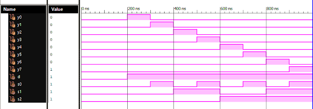
Verilog: 1to 8 DeMultiplexer (1-8 DEMUX) Dataflow Modelling with Testbench Code
Verilog Code for 1 to 8 DeMultiplexer Dataflow Modelling module demux_1_to_8( input d, input s0, input s1, input s2, output y0, output y1, output y2, output y3, output y4, output y5, output y6, output y7 ); assign s0n = ~ s0; assign s1n = ~ s1; assign s2n = ~ s2; assign y0 = d & s0n & s1n & s2n; assign y1 = d & s0 & s1n & s2n; assign y2 = d & s0n & s1 & s2n; assign y3 = d & s0 & s1 & s2n; assign y4 = d & s0n & s1n & s2; assign y5 = d & s0 & s1n & s2; assign y6 = d & s0n & s1 & s2; assign y7 = d & s0 & s1 & s2; endmodule //Testbench code for 1-8 DEMUX Dataflow Modelling initial begin // Initialize Inputs d = 0;s0 = 0;s1 = 0;s2 = 0; // Wait 100 ns for global reset to finish #100; // Add stimulus here #100; d = 1;s0 = 0;s1 = 0;s2 = 0; #100; d = 1;s0 = 1;s1 = 0;s2 = 0; #100; d = 1;s0 = 0;s1 = 1;s2 = 0; #100; d = 1;s0 = 1;s1 = 1;s2 = 0; #100; d = 1;s0 = 0;s1 = 0;s2 = 1; ...


Comments
Post a Comment