Posts
Barcode Generator Tool Free

Free Generate Barcode using Javascript and HTML: Barcode Generator tool is an innovative tool to generate different types of barcodes. This tool made using Javascript, CSS and HTML. An ultimate tool to generate different type of barcodes. An interesting aspect of using this tool is that this tool can work even in offline mode. As javascript and css files are integrated inside HTML itself. You can generate different types of barcodes. Change the foreground and background colors, change the font style, change the font color, vary the size to barcode, size of font, etc. An interesting tool for javascript enthusiastic. Download the source code from the below given button and start exploring different types of barcodes !! Watch Youtube Tutorial Video: Watch the Youtube video to see how the settings work, and feel free to modify the code. This is just the beta version, tasks to do: Implement a javascript to save the barcode on your computer. Barcode is generated in "svg" format. ...
Popular posts from this blog
Samir Palnitkar Solution Manual Free Download PDF of Verilog HDL

This is a solution guide to the exercises of the book "The Solution Manual of the Verilog HDL: A Guide to Digital Design and Synthesis by Samir Palnitkar". Following are the Solutions to Solution Manual on Verilog HDL: A Guide to Digital Design and Synthesis by Samir Palnitkar , exercises of all chapters in the book. Chapter 1 ----------------- No Exercises ---------------- Chapter 2 : Hierarchical Modeling Concepts Chapter 3 : Basic Concepts Chapter 4 : Modules and Ports Chapter 5: Gate-level Modeling Chapter 6 : Dataflow Modeling Chapter 7 : Behavioral Modeling Chapter 8 : Tasks and Functions Download Solution Manual: Click on this link (Mega.nz Link) [Solution Manual to Verilog HDL: A Guide to Digital Design and Synthesis by Samir Palnitkar] Preview of Solution Manual: For Verilog Programs: Go to Index of Verilog Programming Tags: Verilog HDL solutio...
Verilog: 4 Bit Full Adder Behavioral Modelling with Testbench Code
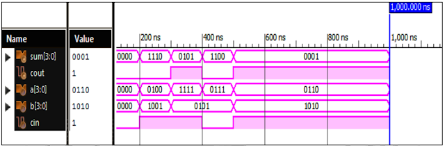
Verilog Code for 4 Bit Full Adder Behavioral Modelling with Testbench Code module 4_bit_Add( input [3:0]a,b, input cin, output [3:0]sum, output cout ); reg [3:0]sum; reg cout; always @ (a or b or cin) assign {cout,sum}= a + b + cin; endmodule //Testbench code for 4 Bit Full Adder Behavioral Modelling initial begin // Initialize Inputs a = 0; b = 0; cin = 0; // Wait 100 ns for global reset to finish #100; // Add stimulus here #100 a=4; b=9; cin=1; #100 a=15; b=5; cin=1; #100 a=7; b=5; cin=0; #100 a=6; b=10; cin=1; end initial begin #100 $monitor (“ a = %b, b = %b, cin = %b, sum = %b, cout = %b”, a, b, cin, sum, cout); end endmodule Xillinx Output: 4 Bit Full Adder Behavioral Modelling Response Also See: List of Verilog Programs
VLSI: 4-1 MUX Dataflow Modelling with Testbench
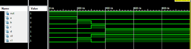
Verilog Code for 4-1 MUX Dataflow Modelling module m41(out, i0, i1, i2, i3, s0, s1); output out; input i0, i1, i2, i3, s0, s1; assign y0 = (i0 & (~s0) & (~s1)); assign y1 = (i1 & (~s0) & s1); assign y2 = (i2 & s0 & (~s1)); assign y3 = (i3 & s0 & s1); assign out = (y0 | y1 | y2 | y3); endmodule //Testbench code for 4-1 MUX Dataflow Modelling initial begin // Initialize Inputs a = 1;b = 0;c = 0;d = 0;s0 = 0;s1 = 0; ...
Verilog: 4 Bit Counter Behavioral Modelling using If Else Statement

Verilog Code for 4 Bit Counter Behavioral Modelling using If Else Statement module 4_bit_Count( input clock, reset, output [3:0]dout ); reg [3:0]dout; initial dout = 0; always @ (posedge (clock)) begin if (reset) dout <= 0; else dout <= dout + 1; end endmodule Xillinx Output: 4 Bit Counter Behavioral Modelling Response Also See: List of Verilog Programs
Verilog: 1to 8 DeMultiplexer (1-8 DEMUX) Dataflow Modelling with Testbench Code
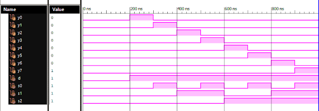
Verilog Code for 1 to 8 DeMultiplexer Dataflow Modelling module demux_1_to_8( input d, input s0, input s1, input s2, output y0, output y1, output y2, output y3, output y4, output y5, output y6, output y7 ); assign s0n = ~ s0; assign s1n = ~ s1; assign s2n = ~ s2; assign y0 = d & s0n & s1n & s2n; assign y1 = d & s0 & s1n & s2n; assign y2 = d & s0n & s1 & s2n; assign y3 = d & s0 & s1 & s2n; assign y4 = d & s0n & s1n & s2; assign y5 = d & s0 & s1n & s2; assign y6 = d & s0n & s1 & s2; assign y7 = d & s0 & s1 & s2; endmodule //Testbench code for 1-8 DEMUX Dataflow Modelling initial begin // Initialize Inputs d = 0;s0 = 0;s1 = 0;s2 = 0; // Wait 100 ns for global reset to finish #100; // Add stimulus here #100; d = 1;s0 = 0;s1 = 0;s2 = 0; #100; d = 1;s0 = 1;s1 = 0;s2 = 0; #100; d = 1;s0 = 0;s1 = 1;s2 = 0; #100; d = 1;s0 = 1;s1 = 1;s2 = 0; #100; d = 1;s0 = 0;s1 = 0;s2 = 1; ...