Posts
VLSI: AND Gate Dataflow Modelling with Testbench

Verilog Code for AND gate Dataflow Modelling module ANDgate( input a, input b, output c ); assign c = a & b; endmodule //Testbench code for AND gate Dataflow Modelling initial begin // Initialize Inputs a = 0;b = 0; // Wait 100 ns for global reset to finish #100 a = 0; b = 1; #100 a = 1; b = 0; #100 a = 1; b = 1; e nd Output:
VLSI: 1 Bit Magnitude Comparator Dataflow Modelling with Testbench
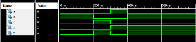
Verilog Code for 1 Bit Magnitude Comparator Dataflow Modelling module comparator_1_bit( input x, input y, output a, //x>y output b, //x=y output c //x<y ); assign xn = ~ x; assign yn = ~ y; assign a = x & yn; assign c = xn & y; assign b = ~ ( a | c ); endmodule //Testbench code for 1 Bit Magnitude Comparator Dataflow Modelling initial begin // Initialize Inputs ...
Barcode Generator Tool Free

Free Generate Barcode using Javascript and HTML: Barcode Generator tool is an innovative tool to generate different types of barcodes. This tool made using Javascript, CSS and HTML. An ultimate tool to generate different type of barcodes. An interesting aspect of using this tool is that this tool can work even in offline mode. As javascript and css files are integrated inside HTML itself. You can generate different types of barcodes. Change the foreground and background colors, change the font style, change the font color, vary the size to barcode, size of font, etc. An interesting tool for javascript enthusiastic. Download the source code from the below given button and start exploring different types of barcodes !! Watch Youtube Tutorial Video: Watch the Youtube video to see how the settings work, and feel free to modify the code. This is just the beta version, tasks to do: Implement a javascript to save the barcode on your computer. Barcode is generated in "svg" format. ...
Optimization: Interval Halving Method

1. Interval Halving Method Algorithm in C #include<stdio.h> double myFun(double x); int main() { double a, b, y, x, xm, x1, x2, fx1, fx2, fxm, L, t=0.01; printf("Enter a:"); scanf("%lf",&a); //Upper Bound printf("Enter b:"); scanf("%lf",&b); //Lower Bound xm = (a + b)/2; jump: L = b-a; x1 = a + (L/4); x2 = b - (L/4); printf("\n\na = %.2lf",a); printf("\nb = %.2lf",b); printf("\nx1 = %.2lf",x1); printf("\nx2 = %.2lf",x2); printf("\nxm = %.2lf",xm); printf("\nL = %.2lf",L); fx1 = myFun(x1); printf("\nf(x1) = %.2lf",fx1); fx2 = myFun(x2); printf("\nf(x2) = %.2lf",fx2); fxm = myFun(xm); printf("\nf(xm) = %.2lf",fxm); if(L > t) { if (fx1 < fxm) { a = a; b = xm; xm = x1; got...
C Program: Show Address of Variable using Pointers
#include<stdio.h> #include<conio.h> void main() { int a=12; float b=24.25; char c='a'; clrscr(); printf("\n Address of A : %u",&a); printf("\n Address of B : %u",&b); printf("\n Address of C : %u",&c); getch(); } Output: Address of A : 65524 Address of B : 65520 Address of C : 65519 C Programs: ------------------------ | Basic Programs | Loop Programs | Conditional Programs | Matrix Programs | Array Programs | String Programs | File Handling | Other Programs | Graphics in C | Pattern Programs ------------------------
4 Pole Bandpass Active Filter Calculator

4 Pole Bandpass Active Filter Input Output Filter Type Butterworth Chebyshev 0.1 dB Bessel Capacitors (uF) Center Freq (Hz) 3dB Bandwidth (Hz) Voltage Gain C1,C2,C3,C4 (uF) R1 (K Ohms) R2 (K Ohms) R3 (K Ohms) R4 (K Ohms) R5 (K Ohms) R6 (K Ohms) Section 1 2 Q Freq Active Lowpass Calculator: 1. 2 Pole Active Lowpass with Unity Gain 2. 2 Pole Active Lowpass with Gain 3. 3 Pole Active Lowpass Filter Active Highpass Calculator: 1. 2 Pole Active Highpass with Unity Gain 2. 2 Pole Active Highpass with Gain 3. 3 Pole Active Highpass Filter Active Bandpass Calculator: 1. 2 Pole Active BandPass Filter 2. 4 Pole Active BandPass Filter 3. 6 Pole Active BandPass Filter
Filter Designer
Filter Designer Filter Designer tool can be used for designing Active Lowpass, Active Highpass and Active Bandpass Filters. Calculate the values of capacitors, resistors, Q values and frequencies of active filter. Note: Filter Designer Tool works best on Computers, we are currently optimizing this tool to work on smartphones. -------------------------------------------------------- Active Lowpass Calculator: 1. 2 Pole Active Lowpass with Unity Gain 2. 2 Pole Active Lowpass with Gain 3. 3 Pole Active Lowpass Filter Active Highpass Calculator: 1. 2 Pole Active Highpass with Unity Gain 2. 2 Pole Active Highpass with Gain 3. 3 Pole Active Highpass Filter Active Bandpass Calculator: 1. 2 Pole Active BandPass Filter 2. 4 Pole Active BandPass Filter 3. 6 Pole Active BandPass Filter Notch Filter Calculator: 1. 2 Op-Amp Notch Filter Calculator Sallen Key Filter Calculator: 1. Sallen Key Lowpass Butterworth Filter Calculator
Popular posts from this blog
VLSI: 8-3 Encoder Dataflow Modelling with Testbench

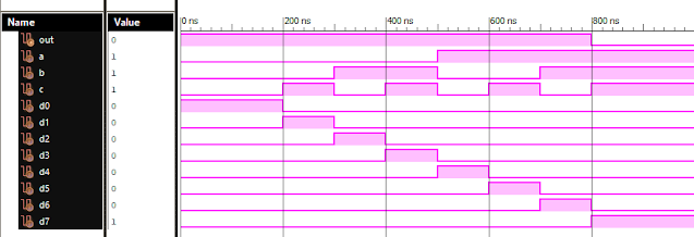
Verilog Code for 8-3 Encoder Dataflow Modelling module encoder_8_to_3( input d0, input d1, input d2, input d3, input d4, input d5, input d6, input d7, output q0, output q1, output q2 ); assign q0 = ( d1 | d3 | d5 | d7 ); assign q1 = ( d2 | d3 | d6 | d7 ); assign q2 = ( d4 | d6 | d5 | d7 ); endmodule //Testbench code for 8-3 Encoder Dataflow Modelling initial begin ...
Verilog: 8 to 1 Multiplexer (8-1 MUX) Dataflow Modelling with Testbench Code
Verilog Code for 8 to 1 Multiplexer Dataflow Modelling module mux_8to1( input a, input b, input c, input D0, input D1, input D2, input D3, input D4, input D5, input D6, input D7, output out, ); module m81( output out, input D0, D1, D2, D3, D4, D5, D6, D7, S0, S1, S2); assign S1bar=~S1; assign S0bar=~S0; assign S2bar=~S2; assign out = (D0 & S2bar & S1bar & S0bar) | (D1 & S2bar & S1bar & S0) | (D2 & S2bar & S1 & S0bar) + (D3 & S2bar & S1 & S0) + (D4 & S2 & S1bar & S0bar) + (D5 & S2 & S1bar & S0) + (D6 & S2 & S1 & S0bar) + (D7 & S2 & S1 & S0); endmodule //Testbench code for 8-1 MUX Dataflow Modelling initial begin // Initialize Inputs a= 0;b = 0;c = 0;D0 = 1;D1 = 0;D2 = 0;D3 = 0;D4 = 0;D5 = 0;D6 = 0;D7 = 0; // Wait 100 ns for global reset to finish #100; // Add stimulus here #100; a = 0;b = 0;c = 1;d0 = ...
VLSI: 4-1 MUX Dataflow Modelling with Testbench
Verilog Code for 4-1 MUX Dataflow Modelling module m41(out, i0, i1, i2, i3, s0, s1); output out; input i0, i1, i2, i3, s0, s1; assign y0 = (i0 & (~s0) & (~s1)); assign y1 = (i1 & (~s0) & s1); assign y2 = (i2 & s0 & (~s1)); assign y3 = (i3 & s0 & s1); assign out = (y0 | y1 | y2 | y3); endmodule //Testbench code for 4-1 MUX Dataflow Modelling initial begin // Initialize Inputs a = 1;b = 0;c = 0;d = 0;s0 = 0;s1 = 0; ...
Verilog: 4 to 1 Multiplexer Behavioral Modelling with Testbench Code
Verilog Code 4-1 Multiplexer Behavioral Modelling using Case Statement module Mux_4to1 ( input [3:0] i, input s1, s0, output out ); always @(i or s1 or s0) case({s1, s0}) 0 : out = i[0]; 1 : out = i[1]; 2 : out = i[2]; 3 : out = i[3]; default : out = 1’bx; endcase endmodule // test-bench initial begin i=1'b1010; s1=0; s0=0; #100; //wait 100ns for global reset to finish //add stimulus here #100 s1 = 0; s0= 1; #100 s1 = 1; s0= 0; #100 s1 = 1; s0= 1; end
VLSI: 1-4 DEMUX (Demultiplexer) Dataflow Modelling with Testbench

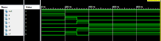
Verilog Code for 1-4 DEMUX Dataflow Modelling module demux_1_to_4( input d, input s0, input s1, output y0, output y1, output y2, output y3 ); assign s1n = ~ s1; assign s0n = ~ s0; assign y0 = d& s0n & s1n; assign y1 = d & s0 & s1n; assign y2 = d & s0n & s1; assign y3 = d & s0 & s1; endmodule //Testbench code for 1-4 DEMUX Dataflow Modelling initial begin // Initialize Inputs ...