Posts
Verilog: 8 to 3 Encoder Dataflow Modelling with Testbench Code
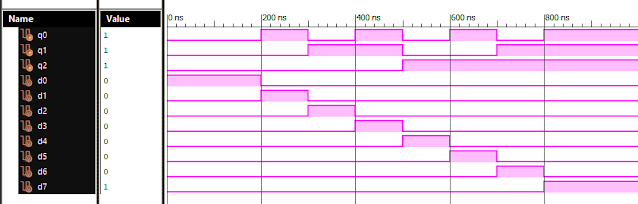
Verilog Code for 8 to 3 Encoder Dataflow Modelling module encoder_8_to_3( input d0, input d1, input d2, input d3, input d4, input d5, input d6, input d7, output q0, output q1, output q2 ); assign q0 = ( d1 | d3 | d5 | d7 ); assign q1 = ( d2 | d3 | d6 | d7 ); assign q2 = ( d4 | d6 | d5 | d7 ); endmodule //Testbench initial begin // Initialize Inputs d0 = 1; d1 = 0; d2 = 0; d3 = 0; d4 = 0; d5 = 0; d6 = 0; d7 = 0; // Wait 100 ns for global reset to finish #100; // Add stimulus here #100;d0 = 0;d1 = 1;d2 = 0;d3 = 0;d4 = 0;d5 = 0;d6 = 0;d7 = 0; #100;d0 = 0;d1 = 0;d2 = 1;d3 = 0;d4 = 0;d5 = 0;d6 = 0;d7 = 0; #100;d0 = 0;d1 = 0;d2 = 0;d3 = 1;d4 = 0;d5 = 0;d6 = 0;d7 = 0; #100;d0 = 0;d1 = 0;d2 = 0;d3 = 0;d4 = 1;d5 = 0;d6 = 0;d7 = 0; #100;d0 = 0;d1 = 0;d2 = 0;d3 = 0;d4 = 0;d5 = 1;d6 = 0;d7 = 0; #100;d0 = 0;d1 = 0;d2 = 0;d3 = 0;d4 = 0;d5 = 0;d6 = 1;d7 = 0; #100;d0 = 0;d1 = 0;d2 = 0;d3 = 0;d4 = 0;d5 = 0;d6 = 0;d7 = 1; end Xillinx Output: 8 to 3 Encoder Xilinx Output ...
Verilog: 1to 8 DeMultiplexer (1-8 DEMUX) Dataflow Modelling with Testbench Code
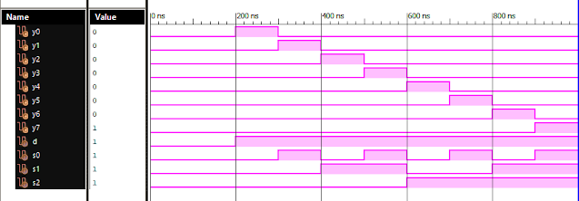
Verilog Code for 1 to 8 DeMultiplexer Dataflow Modelling module demux_1_to_8( input d, input s0, input s1, input s2, output y0, output y1, output y2, output y3, output y4, output y5, output y6, output y7 ); assign s0n = ~ s0; assign s1n = ~ s1; assign s2n = ~ s2; assign y0 = d & s0n & s1n & s2n; assign y1 = d & s0 & s1n & s2n; assign y2 = d & s0n & s1 & s2n; assign y3 = d & s0 & s1 & s2n; assign y4 = d & s0n & s1n & s2; assign y5 = d & s0 & s1n & s2; assign y6 = d & s0n & s1 & s2; assign y7 = d & s0 & s1 & s2; endmodule //Testbench code for 1-8 DEMUX Dataflow Modelling initial begin // Initialize Inputs d = 0;s0 = 0;s1 = 0;s2 = 0; // Wait 100 ns for global reset to finish #100; // Add stimulus here #100; d = 1;s0 = 0;s1 = 0;s2 = 0; #100; d = 1;s0 = 1;s1 = 0;s2 = 0; #100; d = 1;s0 = 0;s1 = 1;s2 = 0; #100; d = 1;s0 = 1;s1 = 1;s2 = 0; #100; d = 1;s0 = 0;s1 = 0;s2 = 1; ...
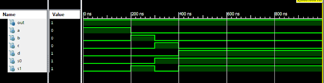
Verilog: 1 to 4 DeMultiplexer (1-4 DEMUX) Dataflow Modelling with Testbench Code
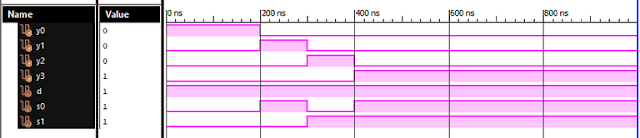
Verilog Code for 1 to 4 DeMultiplexer Dataflow Modelling module demux_1_to_4( input d, input s0, input s1, output y0, output y1, output y2, output y3 ); assign s1n = ~ s1; assign s0n = ~ s0; assign y0 = d& s0n & s1n; assign y1 = d & s0 & s1n; assign y2 = d & s0n & s1; assign y3 = d & s0 & s1; endmodule //Testbench code for 1-4 DEMUX Dataflow Modelling initial begin // Initialize Inputs d = 1; s0 = 0; s1 = 0; // Wait 100 ns for global reset to finish #100; // Add stimulus here #100;d = 1;s0 = 1;s1 = 0; #100;d = 1;s0 = 0;s1 = 1; #100;d = 1;s0 = 1;s1 = 1; end Xillinx Output: 1-4 DEUX Dataflow Modelling Also See: List of Verilog Programs
Verilog: VLSI Code for JK Flip Flop with Testbench Dataflow Modelling
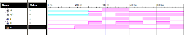
Verilog Code for J K Flip Flop Dataflow Modelling module JK_flipflop( input j, input k, input en, output q, output qb ); assign a = ~ ( qb & j & en ); assign b = ~ ( q & k & en ); assign q = ~ ( a & qb ); assign qb = ~ ( b & q & (~ k) ); endmodule //Testbench initial begin // Initialize Inputs j = 0; k = 0; en = 0; // Wait 100 ns for global reset to finish #100; // Add stimulus here #100;j = 0;k = 0;en = 1; #100;j = 0;k = 1;en = 1; #100;j = 1;k = 0;en = 1; #100;j = 1;k = 1;en = 1; #100;j = 0;k = 1;en = 0; #100;j = 1;k = 0;en = 0; #100;j = 1;k = 1;en = 0; #100;j = 0;k = 0;en = 1; #100;j = 0;k = 1;en = 1; #100;j = 1;k = 0;en = 1; #100;j = 1;k = 1;en = 1; end Xillinx Output: JK Flip Flop Dataflow Modelling Also See: List of Verilog Programs
Popular posts from this blog
VLSI: 8-3 Encoder Dataflow Modelling with Testbench

Verilog Code for 8-3 Encoder Dataflow Modelling module encoder_8_to_3( input d0, input d1, input d2, input d3, input d4, input d5, input d6, input d7, output q0, output q1, output q2 ); assign q0 = ( d1 | d3 | d5 | d7 ); assign q1 = ( d2 | d3 | d6 | d7 ); assign q2 = ( d4 | d6 | d5 | d7 ); endmodule //Testbench code for 8-3 Encoder Dataflow Modelling initial begin ...
Verilog: 8 to 1 Multiplexer (8-1 MUX) Dataflow Modelling with Testbench Code
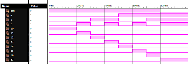
Verilog Code for 8 to 1 Multiplexer Dataflow Modelling module mux_8to1( input a, input b, input c, input D0, input D1, input D2, input D3, input D4, input D5, input D6, input D7, output out, ); module m81( output out, input D0, D1, D2, D3, D4, D5, D6, D7, S0, S1, S2); assign S1bar=~S1; assign S0bar=~S0; assign S2bar=~S2; assign out = (D0 & S2bar & S1bar & S0bar) | (D1 & S2bar & S1bar & S0) | (D2 & S2bar & S1 & S0bar) + (D3 & S2bar & S1 & S0) + (D4 & S2 & S1bar & S0bar) + (D5 & S2 & S1bar & S0) + (D6 & S2 & S1 & S0bar) + (D7 & S2 & S1 & S0); endmodule //Testbench code for 8-1 MUX Dataflow Modelling initial begin // Initialize Inputs a= 0;b = 0;c = 0;D0 = 1;D1 = 0;D2 = 0;D3 = 0;D4 = 0;D5 = 0;D6 = 0;D7 = 0; // Wait 100 ns for global reset to finish #100; // Add stimulus here #100; a = 0;b = 0;c = 1;d0 = ...
VLSI: 4-1 MUX Dataflow Modelling with Testbench
Verilog Code for 4-1 MUX Dataflow Modelling module m41(out, i0, i1, i2, i3, s0, s1); output out; input i0, i1, i2, i3, s0, s1; assign y0 = (i0 & (~s0) & (~s1)); assign y1 = (i1 & (~s0) & s1); assign y2 = (i2 & s0 & (~s1)); assign y3 = (i3 & s0 & s1); assign out = (y0 | y1 | y2 | y3); endmodule //Testbench code for 4-1 MUX Dataflow Modelling initial begin // Initialize Inputs a = 1;b = 0;c = 0;d = 0;s0 = 0;s1 = 0; ...
Verilog: 4 to 1 Multiplexer Behavioral Modelling with Testbench Code
Verilog Code 4-1 Multiplexer Behavioral Modelling using Case Statement module Mux_4to1 ( input [3:0] i, input s1, s0, output out ); always @(i or s1 or s0) case({s1, s0}) 0 : out = i[0]; 1 : out = i[1]; 2 : out = i[2]; 3 : out = i[3]; default : out = 1’bx; endcase endmodule // test-bench initial begin i=1'b1010; s1=0; s0=0; #100; //wait 100ns for global reset to finish //add stimulus here #100 s1 = 0; s0= 1; #100 s1 = 1; s0= 0; #100 s1 = 1; s0= 1; end
VLSI: 1-4 DEMUX (Demultiplexer) Dataflow Modelling with Testbench

Verilog Code for 1-4 DEMUX Dataflow Modelling module demux_1_to_4( input d, input s0, input s1, output y0, output y1, output y2, output y3 ); assign s1n = ~ s1; assign s0n = ~ s0; assign y0 = d& s0n & s1n; assign y1 = d & s0 & s1n; assign y2 = d & s0n & s1; assign y3 = d & s0 & s1; endmodule //Testbench code for 1-4 DEMUX Dataflow Modelling initial begin // Initialize Inputs ...