Sun - The Ball of Fire
Mysterious Sun:
Electromagnetic winds emmited from Sun are solar winds. Solar winds consists of protons and electrons, when these protons and electrons interact with Earth's magnetic field sky get lit up by different colors. The solar winds are emmited by solar holes in sun, as these solar holes are less dense than other parts of Sun, they provide path to allow the wind outwards to surface of Sun. These winds are thrown out by such a huge force that they can travel very long distances, even reaching to Earth. These winds can have speed up to 1000 Km/sec.
Electromagnetic winds emmited from Sun are solar winds. Solar winds consists of protons and electrons, when these protons and electrons interact with Earth's magnetic field sky get lit up by different colors. The solar winds are emmited by solar holes in sun, as these solar holes are less dense than other parts of Sun, they provide path to allow the wind outwards to surface of Sun. These winds are thrown out by such a huge force that they can travel very long distances, even reaching to Earth. These winds can have speed up to 1000 Km/sec.
 |
| Solar Emission |
Even though we know Sun from centuries,
there are many mysteries of Sun remained unsolved. Most popular mystery is
regarding Corona of Sun. Corona is outer layer of Sun's atmosphere. Corona is
hotter than the inner layer Chromosphere. Sun's visible surface
Photosphere has temperature 5800°C. Outer layer of Photosphere is
Chromosphere. Temperature of Chromosphere is estimated to be 4000°C. But
astonishing fact is that Corona (outermost
layer of Sun) is 3 Million ℃. This is not possible if Heat Transfer laws are to be considered.
To study about Sun in detail NASA sent a probe in 2018, ISRO will send
Aaditya L1 probe to Langlargian L1 point from where Aaditya L1 will study the
properties of Sun.
Diameter : 1.3927 Million Km
Distance From Earth: 150 Million Km
Color: Yellow
Popular posts from this blog
Samir Palnitkar Solution Manual Free Download PDF of Verilog HDL
This is a solution guide to the exercises of the book "The Solution Manual of the Verilog HDL: A Guide to Digital Design and Synthesis by Samir Palnitkar". Following are the Solutions to Solution Manual on Verilog HDL: A Guide to Digital Design and Synthesis by Samir Palnitkar , exercises of all chapters in the book. Chapter 1 ----------------- No Exercises ---------------- Chapter 2 : Hierarchical Modeling Concepts Chapter 3 : Basic Concepts Chapter 4 : Modules and Ports Chapter 5: Gate-level Modeling Chapter 6 : Dataflow Modeling Chapter 7 : Behavioral Modeling Chapter 8 : Tasks and Functions Download Solution Manual: Click on this link (Mega.nz Link) [Solution Manual to Verilog HDL: A Guide to Digital Design and Synthesis by Samir Palnitkar] Preview of Solution Manual: For Verilog Programs: Go to Index of Verilog Programming Tags: Verilog HDL solutio...
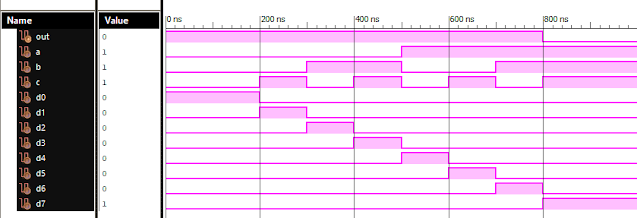
VLSI: 8-3 Encoder Dataflow Modelling with Testbench

Verilog Code for 8-3 Encoder Dataflow Modelling module encoder_8_to_3( input d0, input d1, input d2, input d3, input d4, input d5, input d6, input d7, output q0, output q1, output q2 ); assign q0 = ( d1 | d3 | d5 | d7 ); assign q1 = ( d2 | d3 | d6 | d7 ); assign q2 = ( d4 | d6 | d5 | d7 ); endmodule //Testbench code for 8-3 Encoder Dataflow Modelling initial begin ...
VLSI: 4-1 MUX Dataflow Modelling with Testbench
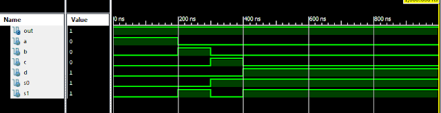
Verilog Code for 4-1 MUX Dataflow Modelling module m41(out, i0, i1, i2, i3, s0, s1); output out; input i0, i1, i2, i3, s0, s1; assign y0 = (i0 & (~s0) & (~s1)); assign y1 = (i1 & (~s0) & s1); assign y2 = (i2 & s0 & (~s1)); assign y3 = (i3 & s0 & s1); assign out = (y0 | y1 | y2 | y3); endmodule //Testbench code for 4-1 MUX Dataflow Modelling initial begin // Initialize Inputs a = 1;b = 0;c = 0;d = 0;s0 = 0;s1 = 0; ...
Full Subtractor Verilog Code in Structural/Gate Level Modelling with Testbench

Verilog Code for Full Subtractor Structural/Gate Level Modelling module full_sub(borrow,diff,a,b,c); output borrow,diff; input a,b,c; wire w1,w4,w5,w6; xor (diff,a,b,c); not n1(w1,a); and a1(w4,w1,b); and a2(w5,w1,c); and a3(w6,b,c); or o1(borrow,w4,w5,w6); endmodule //Testbench code for Full Subtractor Structural/Gate Level Modelling initial begin // Initialize Inputs a = 0; b = 0; c = 0; // Wait 100 ns for global reset to finish #100; // Add stimulus here #100; a = 0;b = 0;c = 1; #100; a = 0;b = 1;c = 0; #100; a = 0;b = 1;c = 1; #100; a = 1;b = 0;c = 0; #100; a = 1;b = 0;c = 1; #100; a = 1;b = 1;c = 0; #100; a = 1;b = 1;c = 1; end Output: RTL Schematic: Full Subtractor Verilog Other Verilog Programs: Go to Index of Verilog Programming
Verilog: 8 to 1 Multiplexer (8-1 MUX) Dataflow Modelling with Testbench Code
Verilog Code for 8 to 1 Multiplexer Dataflow Modelling module mux_8to1( input a, input b, input c, input D0, input D1, input D2, input D3, input D4, input D5, input D6, input D7, output out, ); module m81( output out, input D0, D1, D2, D3, D4, D5, D6, D7, S0, S1, S2); assign S1bar=~S1; assign S0bar=~S0; assign S2bar=~S2; assign out = (D0 & S2bar & S1bar & S0bar) | (D1 & S2bar & S1bar & S0) | (D2 & S2bar & S1 & S0bar) + (D3 & S2bar & S1 & S0) + (D4 & S2 & S1bar & S0bar) + (D5 & S2 & S1bar & S0) + (D6 & S2 & S1 & S0bar) + (D7 & S2 & S1 & S0); endmodule //Testbench code for 8-1 MUX Dataflow Modelling initial begin // Initialize Inputs a= 0;b = 0;c = 0;D0 = 1;D1 = 0;D2 = 0;D3 = 0;D4 = 0;D5 = 0;D6 = 0;D7 = 0; // Wait 100 ns for global reset to finish #100; // Add stimulus here #100; a = 0;b = 0;c = 1;d0 = ...
Comments
Post a Comment