Latest Post
C Program for Level Sketch
- Get link
- X
- Other Apps
C Level Sketch:
#include<stdio.h>
#include<conio.h>
#include<math.h>
int main()
{
float th,ov, HH,H,L,LL,lowTap,UpTap,CC,HH1,H1,L1,LL1,HHper,Hper,Lper,LLper,BtTap;
char ch;
do
{
printf("\nEnter Tank Height in mm:");
scanf("%f",&th);
printf("\nHeight of HH:");
scanf("%f",&HH);
printf("\nHeight of H:");
scanf("%f",&H);
printf("\nHeight of L:");
scanf("%f",&L);
printf("\nHeight of LL:");
scanf("%f",&LL);
printf("\nEnter Height of Overflow Nozzle (if required):");
scanf("%f",&ov);
if (ov != 0)
{
th = ov;
}
else
{
th = th;
}
printf("Height Valid: %.2f",th);
HHper = (HH * 100)/th;
Hper = (H * 100)/th;
Lper = (L * 100)/th;
LLper = (LL * 100)/th;
if (HHper < 90 && LLper > 10)
{
printf("\nAlarm Positions are Valid.");
}
else
{
printf("\nChange Alarm Positions.");
}
printf("\nEstimate Lower Tapping Height:");
scanf("%f",&lowTap);
printf("\nEstimate Upper Tapping Height:");
scanf("%f",&UpTap);
printf("\nEstimate Bottom Pipe(Enter zero if not required):");
scanf("%f",&BtTap);
if (BtTap == 0)
{
CC = UpTap - lowTap;
HH1 = HH - lowTap;
H1 = H - lowTap;
L1 = L - lowTap;
LL1 = LL - lowTap;
}
else
{
CC = UpTap + BtTap;
HH1 = HH + BtTap;
H1 = H + BtTap;
L1 = L + BtTap;
LL1 = LL + BtTap;
}
printf("\n C-C Distance is %f",CC);
HHper = (HH1 * 100)/CC;
Hper = (H1 * 100)/CC;
Lper = (L1 * 100)/CC;
LLper = (LL1 * 100)/CC;
printf("\nHH percentage: %.2f",HHper);
printf("\nH percentage: %.2f",Hper);
printf("\nL percentage: %.2f",Lper);
printf("\nLL percentage: %.2f",LLper);
if (HHper < 90 && LLper > 10)
{
printf("\nTapping Positions are Valid.");
}
else
{
printf("\nChange Tapping Positions.");
}
printf ("\n\nDo you want to repeat the operation Y/N: ");
scanf (" %c", &ch);
}
while (ch == 'y' || ch == 'Y');
return 0;
}
- Get link
- X
- Other Apps
Popular posts from this blog
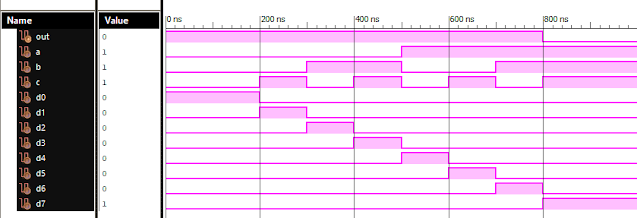
Verilog: 8 to 1 Multiplexer (8-1 MUX) Dataflow Modelling with Testbench Code
Verilog Code for 8 to 1 Multiplexer Dataflow Modelling module mux_8to1( input a, input b, input c, input D0, input D1, input D2, input D3, input D4, input D5, input D6, input D7, output out, ); module m81( output out, input D0, D1, D2, D3, D4, D5, D6, D7, S0, S1, S2); assign S1bar=~S1; assign S0bar=~S0; assign S2bar=~S2; assign out = (D0 & S2bar & S1bar & S0bar) | (D1 & S2bar & S1bar & S0) | (D2 & S2bar & S1 & S0bar) + (D3 & S2bar & S1 & S0) + (D4 & S2 & S1bar & S0bar) + (D5 & S2 & S1bar & S0) + (D6 & S2 & S1 & S0bar) + (D7 & S2 & S1 & S0); endmodule //Testbench code for 8-1 MUX Dataflow Modelling initial begin // Initialize Inputs a= 0;b = 0;c = 0;D0 = 1;D1 = 0;D2 = 0;D3 = 0;D4 = 0;D5 = 0;D6 = 0;D7 = 0; // Wait 100 ns for global reset to finish #100; // Add stimulus here #100; a = 0;b = 0;c = 1;d0 = ...
VLSI: 1-4 DEMUX (Demultiplexer) Dataflow Modelling with Testbench
Verilog Code for 1-4 DEMUX Dataflow Modelling module demux_1_to_4( input d, input s0, input s1, output y0, output y1, output y2, output y3 ); assign s1n = ~ s1; assign s0n = ~ s0; assign y0 = d& s0n & s1n; assign y1 = d & s0 & s1n; assign y2 = d & s0n & s1; assign y3 = d & s0 & s1; endmodule //Testbench code for 1-4 DEMUX Dataflow Modelling initial begin // Initialize Inputs ...
VLSI: 8-3 Encoder Dataflow Modelling with Testbench
Verilog Code for 8-3 Encoder Dataflow Modelling module encoder_8_to_3( input d0, input d1, input d2, input d3, input d4, input d5, input d6, input d7, output q0, output q1, output q2 ); assign q0 = ( d1 | d3 | d5 | d7 ); assign q1 = ( d2 | d3 | d6 | d7 ); assign q2 = ( d4 | d6 | d5 | d7 ); endmodule //Testbench code for 8-3 Encoder Dataflow Modelling initial begin ...
VLSI: 4-1 MUX Dataflow Modelling with Testbench
Verilog Code for 4-1 MUX Dataflow Modelling module m41(out, i0, i1, i2, i3, s0, s1); output out; input i0, i1, i2, i3, s0, s1; assign y0 = (i0 & (~s0) & (~s1)); assign y1 = (i1 & (~s0) & s1); assign y2 = (i2 & s0 & (~s1)); assign y3 = (i3 & s0 & s1); assign out = (y0 | y1 | y2 | y3); endmodule //Testbench code for 4-1 MUX Dataflow Modelling initial begin // Initialize Inputs a = 1;b = 0;c = 0;d = 0;s0 = 0;s1 = 0; ...
Verilog: 1to 8 DeMultiplexer (1-8 DEMUX) Dataflow Modelling with Testbench Code
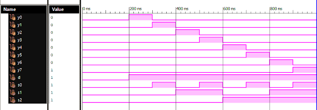
Verilog Code for 1 to 8 DeMultiplexer Dataflow Modelling module demux_1_to_8( input d, input s0, input s1, input s2, output y0, output y1, output y2, output y3, output y4, output y5, output y6, output y7 ); assign s0n = ~ s0; assign s1n = ~ s1; assign s2n = ~ s2; assign y0 = d & s0n & s1n & s2n; assign y1 = d & s0 & s1n & s2n; assign y2 = d & s0n & s1 & s2n; assign y3 = d & s0 & s1 & s2n; assign y4 = d & s0n & s1n & s2; assign y5 = d & s0 & s1n & s2; assign y6 = d & s0n & s1 & s2; assign y7 = d & s0 & s1 & s2; endmodule //Testbench code for 1-8 DEMUX Dataflow Modelling initial begin // Initialize Inputs d = 0;s0 = 0;s1 = 0;s2 = 0; // Wait 100 ns for global reset to finish #100; // Add stimulus here #100; d = 1;s0 = 0;s1 = 0;s2 = 0; #100; d = 1;s0 = 1;s1 = 0;s2 = 0; #100; d = 1;s0 = 0;s1 = 1;s2 = 0; #100; d = 1;s0 = 1;s1 = 1;s2 = 0; #100; d = 1;s0 = 0;s1 = 0;s2 = 1; ...


Comments
Post a Comment