Inkarnate - Fantasy Map Maker
Inkarnate Maps
Inkarnate is a fantasy map making online tool, used to make DnD (Dragons and Dungeons) maps, Battle maps, fantasy World maps for games and novels. Inkarnate is easy to use and with lots of features. Inkarnate has free as well as pro services. For professional map makers I would suggest to use its pro services which has 5$ for a month and 25$ for a year plans. Free services is majorly for hobbyists who want to try till cool map making tool. Although you can make attractive maps using free Inkarnate account, pro services fives you more assets, better resolution of maps (upto 4K), and many other features.
Below I have uploaded some fantasy maps made by me,
Village [Settlement Map]:

Gamora [Settlement Map]:

Map Making Tips for Inkarnate:
1. Jagged coastlines - If your coastline is just a straight line, it will look artificially made. Natural coastlines have curves and jagged edges and little islands or rocks next to them as a result of erosion by waves.
2. Rivers - A lot of people forget that rivers flow from higher elevation to lower elevation and that they meander as they become slower. Again, a straight line won't do (that's not a river, that's a canal) and never have river diverge into two separate rivers. Rivers don't do that - they converge into a bigger river.
3. Areas with different climates - If you want to have a desert or arctic area next to your grasslands/plains area, you need to separate it somehow. The easiest thing to is put in a mountain range which can act as a barrier between them.
4. Underwater Objects - You can create underwater objects by using opacity features of Inkarnate (only available in pro version).
Outpost 1 [Battlemap]:

Outpost 3 [Battlemap]:

Link to Inkarnate: https://inkarnate.com/
Inkarnate Tutorials:
Also See:
Popular posts from this blog
Samir Palnitkar Solution Manual Free Download PDF of Verilog HDL

This is a solution guide to the exercises of the book "The Solution Manual of the Verilog HDL: A Guide to Digital Design and Synthesis by Samir Palnitkar". Following are the Solutions to Solution Manual on Verilog HDL: A Guide to Digital Design and Synthesis by Samir Palnitkar , exercises of all chapters in the book. Chapter 1 ----------------- No Exercises ---------------- Chapter 2 : Hierarchical Modeling Concepts Chapter 3 : Basic Concepts Chapter 4 : Modules and Ports Chapter 5: Gate-level Modeling Chapter 6 : Dataflow Modeling Chapter 7 : Behavioral Modeling Chapter 8 : Tasks and Functions Download Solution Manual: Click on this link (Mega.nz Link) [Solution Manual to Verilog HDL: A Guide to Digital Design and Synthesis by Samir Palnitkar] Preview of Solution Manual: For Verilog Programs: Go to Index of Verilog Programming Tags: Verilog HDL solutio...
VLSI: 8-3 Encoder Dataflow Modelling with Testbench

Verilog Code for 8-3 Encoder Dataflow Modelling module encoder_8_to_3( input d0, input d1, input d2, input d3, input d4, input d5, input d6, input d7, output q0, output q1, output q2 ); assign q0 = ( d1 | d3 | d5 | d7 ); assign q1 = ( d2 | d3 | d6 | d7 ); assign q2 = ( d4 | d6 | d5 | d7 ); endmodule //Testbench code for 8-3 Encoder Dataflow Modelling initial begin ...
VLSI: 4-1 MUX Dataflow Modelling with Testbench
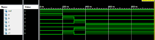
Verilog Code for 4-1 MUX Dataflow Modelling module m41(out, i0, i1, i2, i3, s0, s1); output out; input i0, i1, i2, i3, s0, s1; assign y0 = (i0 & (~s0) & (~s1)); assign y1 = (i1 & (~s0) & s1); assign y2 = (i2 & s0 & (~s1)); assign y3 = (i3 & s0 & s1); assign out = (y0 | y1 | y2 | y3); endmodule //Testbench code for 4-1 MUX Dataflow Modelling initial begin // Initialize Inputs a = 1;b = 0;c = 0;d = 0;s0 = 0;s1 = 0; ...
Verilog: 8 to 1 Multiplexer (8-1 MUX) Dataflow Modelling with Testbench Code
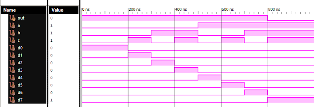
Verilog Code for 8 to 1 Multiplexer Dataflow Modelling module mux_8to1( input a, input b, input c, input D0, input D1, input D2, input D3, input D4, input D5, input D6, input D7, output out, ); module m81( output out, input D0, D1, D2, D3, D4, D5, D6, D7, S0, S1, S2); assign S1bar=~S1; assign S0bar=~S0; assign S2bar=~S2; assign out = (D0 & S2bar & S1bar & S0bar) | (D1 & S2bar & S1bar & S0) | (D2 & S2bar & S1 & S0bar) + (D3 & S2bar & S1 & S0) + (D4 & S2 & S1bar & S0bar) + (D5 & S2 & S1bar & S0) + (D6 & S2 & S1 & S0bar) + (D7 & S2 & S1 & S0); endmodule //Testbench code for 8-1 MUX Dataflow Modelling initial begin // Initialize Inputs a= 0;b = 0;c = 0;D0 = 1;D1 = 0;D2 = 0;D3 = 0;D4 = 0;D5 = 0;D6 = 0;D7 = 0; // Wait 100 ns for global reset to finish #100; // Add stimulus here #100; a = 0;b = 0;c = 1;d0 = ...
Full Subtractor Verilog Code in Structural/Gate Level Modelling with Testbench

Verilog Code for Full Subtractor Structural/Gate Level Modelling module full_sub(borrow,diff,a,b,c); output borrow,diff; input a,b,c; wire w1,w4,w5,w6; xor (diff,a,b,c); not n1(w1,a); and a1(w4,w1,b); and a2(w5,w1,c); and a3(w6,b,c); or o1(borrow,w4,w5,w6); endmodule //Testbench code for Full Subtractor Structural/Gate Level Modelling initial begin // Initialize Inputs a = 0; b = 0; c = 0; // Wait 100 ns for global reset to finish #100; // Add stimulus here #100; a = 0;b = 0;c = 1; #100; a = 0;b = 1;c = 0; #100; a = 0;b = 1;c = 1; #100; a = 1;b = 0;c = 0; #100; a = 1;b = 0;c = 1; #100; a = 1;b = 1;c = 0; #100; a = 1;b = 1;c = 1; end Output: RTL Schematic: Full Subtractor Verilog Other Verilog Programs: Go to Index of Verilog Programming
Comments
Post a Comment