Posts
Verilog: NAND Gate Behavioral Modelling with Testbench Code
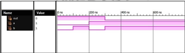
Verilog Code NAND Gate Behavioral Modelling module NAND_GATE ( input a, b, output out ); reg out; always @(a or b) begin if (a==1 & b==1) out = 1’b0; else out = 1’b1; endmodule //test-bench initial begin a=0; b=0; #100; //wait 100ns for global reset to finish //add stimulus here #100 a=0; b=1; #100 a=1; b=0; #100 a=1; b=1; end initial begin #100 $ monitor (“a=%b, b=%b, out=%b”, a, b, out); end endmodule Xilinx Output: NAND Gate Verilog Code Behavioral Modelling
Verilog: AND Gate Behavioral Modelling with Testbench Code
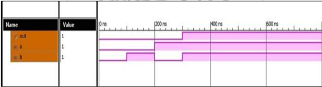
Verilog Code AND Gate Behavioral Modelling module AND_GATE ( input a, b, output out ); reg out; always @(a or b) begin if (a==1 & b==1) out = 1’b1; else out = 1’b0; endmodule //test-bench initial begin a=0; b=0; #100; //wait 100ns for global reset to finish //add stimulus here #100 a=0; b=1; #100 a=1; b=0; #100 a=1; b=1; end initial begin #100 $ monitor (“a=%b, b=%b, out=%b”, a, b, out); end endmodule Xilinx Output: AND Gate Behavioral Response
Verilog: OR Gate Behavioral Modelling with Testbench Code
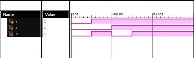
Verilog Code OR Gate Behavioral Modelling module OR_GATE ( input a, b, output out ); reg out; always @(a or b) begin if (a==0 & b==0) out = 1’b0; else out = 1’b1; endmodule //test-bench initial begin a=0; b=0; #100; //wait 100ns for global reset to finish //add stimulus here #100 a=0; b=1; #100 a=1; b=0; #100 a=1; b=1; end initial begin #100 $ monitor (“a=%b, b=%b, out=%b”, a, b, out); end endmodule Xilinx Output: OR Gate Response
Applied Instrumentation GTU (Sem-1) - ME Instrumentation and Control (IC)
1. STUDY MATERIAL for Applied Instrumentation GTU (Sem-1) - ME Instrumentation and Control (IC) SEM 1: Subjects: AIDC (Advanced Industrial Drives and Control) ISC (Intelligent Systems and Control) OTE (Optimization Techniques for Engineers) ESI (Embedded System for Instrumentation) IPR Click on the below given links to download study material: Syllabus Books Notes Study Material Lab Manual Question Papers Assignments Sem 2: ME - Applied Instrumentation Click on the below given link to download study material: Sem 2 Folder Subjects: AVD (Advanced Verilog Design) ISI (Intelligent Sensors and Instrumentation) DC (Digital Control) ASPE (Advanced Signal Processing and Estimation) Disaster Management Also See: Optimization Techniques in C Verilog Programming Filter Designing
Popular posts from this blog
VLSI: 8-3 Encoder Dataflow Modelling with Testbench

Verilog Code for 8-3 Encoder Dataflow Modelling module encoder_8_to_3( input d0, input d1, input d2, input d3, input d4, input d5, input d6, input d7, output q0, output q1, output q2 ); assign q0 = ( d1 | d3 | d5 | d7 ); assign q1 = ( d2 | d3 | d6 | d7 ); assign q2 = ( d4 | d6 | d5 | d7 ); endmodule //Testbench code for 8-3 Encoder Dataflow Modelling initial begin ...
VLSI: 4-1 MUX Dataflow Modelling with Testbench
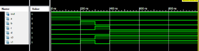
Verilog Code for 4-1 MUX Dataflow Modelling module m41(out, i0, i1, i2, i3, s0, s1); output out; input i0, i1, i2, i3, s0, s1; assign y0 = (i0 & (~s0) & (~s1)); assign y1 = (i1 & (~s0) & s1); assign y2 = (i2 & s0 & (~s1)); assign y3 = (i3 & s0 & s1); assign out = (y0 | y1 | y2 | y3); endmodule //Testbench code for 4-1 MUX Dataflow Modelling initial begin // Initialize Inputs a = 1;b = 0;c = 0;d = 0;s0 = 0;s1 = 0; ...
VLSI: 1-4 DEMUX (Demultiplexer) Dataflow Modelling with Testbench

Verilog Code for 1-4 DEMUX Dataflow Modelling module demux_1_to_4( input d, input s0, input s1, output y0, output y1, output y2, output y3 ); assign s1n = ~ s1; assign s0n = ~ s0; assign y0 = d& s0n & s1n; assign y1 = d & s0 & s1n; assign y2 = d & s0n & s1; assign y3 = d & s0 & s1; endmodule //Testbench code for 1-4 DEMUX Dataflow Modelling initial begin // Initialize Inputs ...
Verilog: 8 to 1 Multiplexer (8-1 MUX) Dataflow Modelling with Testbench Code
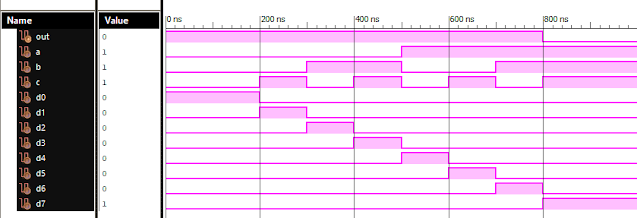
Verilog Code for 8 to 1 Multiplexer Dataflow Modelling module mux_8to1( input a, input b, input c, input D0, input D1, input D2, input D3, input D4, input D5, input D6, input D7, output out, ); module m81( output out, input D0, D1, D2, D3, D4, D5, D6, D7, S0, S1, S2); assign S1bar=~S1; assign S0bar=~S0; assign S2bar=~S2; assign out = (D0 & S2bar & S1bar & S0bar) | (D1 & S2bar & S1bar & S0) | (D2 & S2bar & S1 & S0bar) + (D3 & S2bar & S1 & S0) + (D4 & S2 & S1bar & S0bar) + (D5 & S2 & S1bar & S0) + (D6 & S2 & S1 & S0bar) + (D7 & S2 & S1 & S0); endmodule //Testbench code for 8-1 MUX Dataflow Modelling initial begin // Initialize Inputs a= 0;b = 0;c = 0;D0 = 1;D1 = 0;D2 = 0;D3 = 0;D4 = 0;D5 = 0;D6 = 0;D7 = 0; // Wait 100 ns for global reset to finish #100; // Add stimulus here #100; a = 0;b = 0;c = 1;d0 = ...
Full Subtractor Verilog Code in Behavioral Modelling with Testbench Code
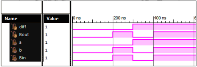
Full Subtractor Verilog Code in Behavioral Modelling module Full_Sub ( input a, b, bin; output diff, borr ); always @(a or b or bin) assign {borr,diff} = (~a) + b + bin; endmodule // test-bench initial begin a=0; b=0; bin=0; #100; //wait 100ns for global reset to finish //add stimulus here #100 a=0; b=1; bin=0; #100 a=1; b=0; bin=0; #100 a=1; b=1; bin=0; end initial begin #100 $ monitor (“a=%b, b=%b, bin=%b, diff=%b, borr=%b”, a, b, bin, diff, borr); end endmodule Xilinx Output: Full Subtractor Verilog Code Behavioral Modelling