Solution Manual: The Solution Manual of the Computer System Architecture by Morris Mano FREE Download PDF
This is a solution guide to the exercises of the book "The Solution Manual of the Computer System Architecture by Morris Mano".
Following are the solutions to Solution Manual on Computer System Architecture by Morris Mano, exercises of all chapters in the book.

Chapter 1 :
Digital Logic Circuits
Chapter 2 :
Digital Components
Chapter 3 :
Data Representation
Chapter 4 :
Register Transfer and Microoperations
Chapter 5:
Basic Computer Organization and Design
Chapter 6 :
Programming the Basic Computer
Chapter 7 :
Microprogrammed Control
Chapter 8 :
Central Processing Unit
Chapter 9 :
Pipeline and Vector Processing
Chapter 10 :
Computer Arithmetic
Chapter 11 :
Input Output Organization
Chapter 12 :
Memory Organization
Chapter 13 :
Multiprocessors
Download Solution Manual:
Click on this link
[Solution Manual to Computer System Architecture by Morris Mano]
Preview of Solution Manual:


For Verilog Programs:
Go to Index of Verilog Programming
Please Report Broken Links in Comment Section...
Popular posts from this blog
Samir Palnitkar Solution Manual Free Download PDF of Verilog HDL
This is a solution guide to the exercises of the book "The Solution Manual of the Verilog HDL: A Guide to Digital Design and Synthesis by Samir Palnitkar". Following are the Solutions to Solution Manual on Verilog HDL: A Guide to Digital Design and Synthesis by Samir Palnitkar , exercises of all chapters in the book. Chapter 1 ----------------- No Exercises ---------------- Chapter 2 : Hierarchical Modeling Concepts Chapter 3 : Basic Concepts Chapter 4 : Modules and Ports Chapter 5: Gate-level Modeling Chapter 6 : Dataflow Modeling Chapter 7 : Behavioral Modeling Chapter 8 : Tasks and Functions Download Solution Manual: Click on this link (Mega.nz Link) [Solution Manual to Verilog HDL: A Guide to Digital Design and Synthesis by Samir Palnitkar] Preview of Solution Manual: For Verilog Programs: Go to Index of Verilog Programming Tags: Verilog HDL solutio...
VLSI: 8-3 Encoder Dataflow Modelling with Testbench

Verilog Code for 8-3 Encoder Dataflow Modelling module encoder_8_to_3( input d0, input d1, input d2, input d3, input d4, input d5, input d6, input d7, output q0, output q1, output q2 ); assign q0 = ( d1 | d3 | d5 | d7 ); assign q1 = ( d2 | d3 | d6 | d7 ); assign q2 = ( d4 | d6 | d5 | d7 ); endmodule //Testbench code for 8-3 Encoder Dataflow Modelling initial begin ...
VLSI: 4-1 MUX Dataflow Modelling with Testbench
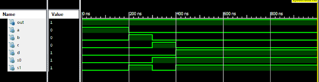
Verilog Code for 4-1 MUX Dataflow Modelling module m41(out, i0, i1, i2, i3, s0, s1); output out; input i0, i1, i2, i3, s0, s1; assign y0 = (i0 & (~s0) & (~s1)); assign y1 = (i1 & (~s0) & s1); assign y2 = (i2 & s0 & (~s1)); assign y3 = (i3 & s0 & s1); assign out = (y0 | y1 | y2 | y3); endmodule //Testbench code for 4-1 MUX Dataflow Modelling initial begin // Initialize Inputs a = 1;b = 0;c = 0;d = 0;s0 = 0;s1 = 0; ...
Full Subtractor Verilog Code in Structural/Gate Level Modelling with Testbench

Verilog Code for Full Subtractor Structural/Gate Level Modelling module full_sub(borrow,diff,a,b,c); output borrow,diff; input a,b,c; wire w1,w4,w5,w6; xor (diff,a,b,c); not n1(w1,a); and a1(w4,w1,b); and a2(w5,w1,c); and a3(w6,b,c); or o1(borrow,w4,w5,w6); endmodule //Testbench code for Full Subtractor Structural/Gate Level Modelling initial begin // Initialize Inputs a = 0; b = 0; c = 0; // Wait 100 ns for global reset to finish #100; // Add stimulus here #100; a = 0;b = 0;c = 1; #100; a = 0;b = 1;c = 0; #100; a = 0;b = 1;c = 1; #100; a = 1;b = 0;c = 0; #100; a = 1;b = 0;c = 1; #100; a = 1;b = 1;c = 0; #100; a = 1;b = 1;c = 1; end Output: RTL Schematic: Full Subtractor Verilog Other Verilog Programs: Go to Index of Verilog Programming
Verilog: 8 to 1 Multiplexer (8-1 MUX) Dataflow Modelling with Testbench Code
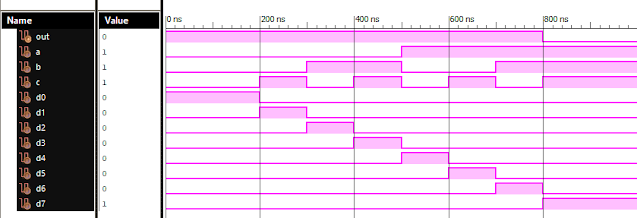
Verilog Code for 8 to 1 Multiplexer Dataflow Modelling module mux_8to1( input a, input b, input c, input D0, input D1, input D2, input D3, input D4, input D5, input D6, input D7, output out, ); module m81( output out, input D0, D1, D2, D3, D4, D5, D6, D7, S0, S1, S2); assign S1bar=~S1; assign S0bar=~S0; assign S2bar=~S2; assign out = (D0 & S2bar & S1bar & S0bar) | (D1 & S2bar & S1bar & S0) | (D2 & S2bar & S1 & S0bar) + (D3 & S2bar & S1 & S0) + (D4 & S2 & S1bar & S0bar) + (D5 & S2 & S1bar & S0) + (D6 & S2 & S1 & S0bar) + (D7 & S2 & S1 & S0); endmodule //Testbench code for 8-1 MUX Dataflow Modelling initial begin // Initialize Inputs a= 0;b = 0;c = 0;D0 = 1;D1 = 0;D2 = 0;D3 = 0;D4 = 0;D5 = 0;D6 = 0;D7 = 0; // Wait 100 ns for global reset to finish #100; // Add stimulus here #100; a = 0;b = 0;c = 1;d0 = ...
Comments
Post a Comment